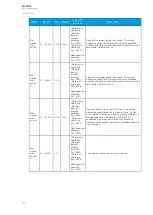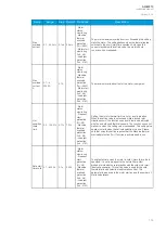
Table. 5.3.11 - 80. Motor data settings.
Name
Range
Step Default
Protection
functions
Description
Motor In
Scaled
0.1... 40.0
x I
n
0.1 x
I
n
-
- Motor status
monitoring
- Machine
thermal
overload
protection
(Tm>; 49M)
- Motor
starting
monitoring
(Ist>; 48)
- Undercurrent
(I<; 37)
- Load jam
protection
(Im>; 51M)
The motor's nominal current scaled to per unit. If the user selects
Object In in the CT settings, this value should be 1.00. If scaled to
the CT nominal, this value may vary.
Motor In
A
0.1...5,000
A
0.1 A -
- Motor status
monitoring
- Machine
thermal
overload
protection
(Tm>; 49M)
- Motor
starting
monitoring
(Ist>; 48)
- Undercurrent
(I<; 37)
- Load jam
protection
(Im>; 51M)
The motor's nominal current in amperes.
No load
current<
0.1…40.0
x I
n
0.1 x
I
n
0.2 x I
n
- Motor status
monitoring
- Machine
thermal
overload
protection
(Tm>; 49M)
- Undercurrent
(I<; 37)
The motor's no load current. This setting defines the "Stopped"
condition when the current is below this setting value. Also, when
the current is below this value, the undercurrent protection stage
is locked.
No load
current<
A
0.1...5 000
A
0.1 A -
- Motor status
monitoring
- Machine
thermal
overload
protection
(Tm>; 49M)
- Undercurrent
(I<; 37)
The motor's no load current in amperes.
Table. 5.3.11 - 81. Pick-up settings.
Name
Description
Range
Step
Default
I
set
Pick-up setting
0.10…40.00xI
n
0.01xI
n
0.5xI
n
The pick-up activation of the function is not directly equal to the START signal generation of the
function. The START signal is allowed if the blocking condition is not active.
A
AQ
Q-M210
-M210
Instruction manual
Version: 2.04
152
Содержание AQ-M210
Страница 1: ...AQ M210 Motor protection IED Instruction manual ...
Страница 308: ...Figure 7 4 182 Example block scheme A AQ Q M210 M210 Instruction manual Version 2 04 307 ...
Страница 329: ...Figure 8 13 204 Panel cutout dimensions and device spacing A AQ Q M210 M210 Instruction manual Version 2 04 328 ...


