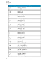
General settings
The following general settings define the general behavior of the function. These settings are static i.e.
it is not possible to change them by editing the setting group.
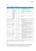
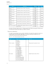
Table. 5.3.15 - 107. General settings of the function.
Name
Description
Range
Step Default
Channel
1
sensors
Defines the amount of sensors connected to channel 1/2/3/4.
0: No
sensors
1: 1 sensor
2: 2 sensors
3: 3 sensors
-
1: No
sensors
Channel
2
sensors
Channel
3
sensors
Channel
4
sensors
Channel
1 sensor
status
Displays the status of the sensor channel. If amount of sensors connected to the
channel don't match with "Channel 1/2/3/4 sensors" setting, this parameter will
go to "Configuration fault" state.
0: Sensors
OK
1:
Configuration
fault state
-
-
Channel
2 sensor
status
Channel
3 sensor
status
Channel
4 sensor
status
Pick-up
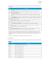
The pick-up of each zone of the Iarc>/I0arc> function is controlled by one of the following: the phase
current pick-up setting, the residual current pick-up setting, or the sensor channels. The pick-up
setting depends on which of these are activated in the zone.
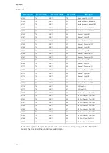
Table. 5.3.15 - 108. Enabled Zone pick-up settings.
Name
Description
Range
Step
Default
Phase current pick-up
The phase current measurement's pick-up value (in p.u.).
0.05...40.00
x I
n
0.01 x
I
n
1.2 x I
n
I0 input selection
Selects the residual current channel (I01 or I02).
0: None
1: I01
2: I02
-
0: None
Res.current pick-up
The residual current measurement's pick-up value (in p.u.).
0.05...40.00
x I
0n
0.01 x
I
0n
1.2 x I
0n
Zone1/2/3/4 Enabled
Enables the chosen zone. Up to 4 zones can be enabled.
0: Disabled
1: Enabled
-
0:
Disabled
Zone1/2/3/4 Ph. curr.
Enabled
The phase overcurrent allows the zone to trip when light is
detected.
0: Disabled
1: Enabled
-
0:
Disabled
Zone1/2/3/4 Res. curr.
Enabled
The residual overcurrent allows the zone to trip when light is
detected.
0: Disabled
1: Enabled
-
0:
Disabled
A
AQ
Q-M210
-M210
Instruction manual
Version: 2.04
204
Содержание AQ-M210
Страница 1: ...AQ M210 Motor protection IED Instruction manual ...
Страница 308: ...Figure 7 4 182 Example block scheme A AQ Q M210 M210 Instruction manual Version 2 04 307 ...
Страница 329: ...Figure 8 13 204 Panel cutout dimensions and device spacing A AQ Q M210 M210 Instruction manual Version 2 04 328 ...


