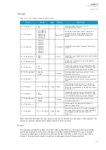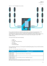
Figure. 5.3.15 - 140. Scheme IA1 (with AQ-200 protection relays).
The settings for the relay supervising the incoming feeder are the same as in the first example. The
relays supervising the busbar and the outgoing feeder, however, have a different setting. Both Zones 2
and 3 need to be enabled as there are sensors connected to both Zone 2 and 3 starts. Sensors
connected to the channel S3 are in Zone 2. Then enable Light 3 of Zone 2. The sensor connected to
the channel S2 is in Zone 3. Then enable Light 2 of Zone 3.
If any of the channels have a pressure sensing sensor, enable it the same way as the regular light
sensors. If either phase overcurrent or residual overcurrent is needed for the tripping decision, they can
be enabled in the same way as light sensors in the zone. When a current channel is enabled, the
measured current needs to be above the set current limit in addition to light sensing.
Measured input
Arc protection uses samples based on current measurements. If the required number of samples is
found to be above the setting limit, the current condition activates. The arc protection can alternatively
use either phase currents or residual currents in the tripping decision.
A
AQ
Q-M210
-M210
Instruction manual
Version: 2.04
203
Содержание AQ-M210
Страница 1: ...AQ M210 Motor protection IED Instruction manual ...
Страница 308: ...Figure 7 4 182 Example block scheme A AQ Q M210 M210 Instruction manual Version 2 04 307 ...
Страница 329: ...Figure 8 13 204 Panel cutout dimensions and device spacing A AQ Q M210 M210 Instruction manual Version 2 04 328 ...


