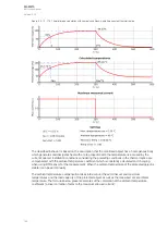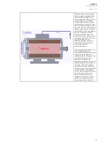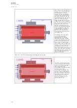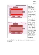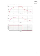
Figure. 5.3.13 - 113. Short time constant thermal image calculation.
Where:
• θ
t-1
= Thermal image status in a previous calculation cycle (the memory of the function)
• I
EM
= (see below)
• I
N
= Current for the 100 % thermal capacity to be used (pick-up current in p.u., with this
current t
max
achieved in time t)
• k
SF
= Loading factor (service factor) coefficient, the maximum allowed load current in
p.u. value, depending on the protected object
• k
AMB
= Temperature correction factor, either from a linear approximation or from a settable
ten-point thermal capacity curve
• e = Euler's number
• t = Calculation time step in seconds (0.005 s)
• τ
2h
= Short thermal heating time constant of the protected object (in minutes)
• τ
2c
= Short thermal cooling time constant of the protected object (in minutes)
• W
f
= Correction factor between the times t
1
and t
2
The equation below is that of the effective current of the protected object including the TRMS
measurement maximum phase current as well as a possible phase current unbalance condition.
Where:
• I
1
= Calculated positive sequence current of the measured RMS phase currents
• I
2
= Calculated negative sequence current of the measured RMS phase currents
• k
NPS
= Correction factor of the NPS current biasing to the equivalent current calculation
• I
MAX
= Measured maximum of the three TRMS phase currents
The thermal image status (θ
t%
, in percentages of the maximum thermal capacity used) calculation is
based on the sum of the long and short time constant thermal image calculation:
The basic operating principle of the thermal replica is based on the nominal temperature rise, which is
achieved when the protected object is loaded with a nominal load in a nominal ambient temperature.
When the object is loaded with a nominal load for a time equal to its heating constant tau (τ), 63% of
the nominal thermal capacity is used. When the loading continues until five times this given constant,
the used thermal capacity approaches 100 % indefinitely but never exceeds it. With a single time
constant model the cooling of the object follows this same behavior, the reverse of the heating when
the current feeding is completely zero.
A
AQ
Q-M210
-M210
Instruction manual
Version: 2.04
162
Содержание AQ-M210
Страница 1: ...AQ M210 Motor protection IED Instruction manual ...
Страница 308: ...Figure 7 4 182 Example block scheme A AQ Q M210 M210 Instruction manual Version 2 04 307 ...
Страница 329: ...Figure 8 13 204 Panel cutout dimensions and device spacing A AQ Q M210 M210 Instruction manual Version 2 04 328 ...


