Name
Range
Step
Default
Prot.funcs.
Description
Max
overload
current
0.1…40.0xI
n
0.1xI
n
2.0xI
n
- motor status
monitoring
- machine
thermal
overload
protection
(TM>; 49M)
- motor start/
locked rotor
monitoring
(Ist>; 48/14)
- mechanical
jam protection
(Im>; 51M)
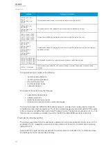
The motor's maximum overload current. Exceeding this
setting stalls the motor. This setting defines when the
thermal replica switches to the short (stall) time constant.
As long as the current stays below this setting value, the
motor should run even when overloaded.
Max
overload
current
A
0.1...5000.0A 0.1A
-
- motor status
monitoring
- machine
thermal
overload
protection
(TM>; 49M)
- motor start/
locked rotor
monitoring
(Ist>; 48/14)
- mechanical
jam protection
(Im>; 51M)
The maximum overload current of the motor in amperes.
No load
current <
0.1…40.0xI
n
0.1xI
n
0.2xI
n
- motor status
monitoring
- machine
thermal
overload
protection
(TM>; 49M)
- non-
directional
undercurrent
protection (I<;
37)
The motor's no load current. This setting defines the
"Stopped" condition when the current is below this setting
value. Also, when the current is below this value, the
undercurrent protection stage is locked.
No load
current <
A
0.1...5000.0A 0.1A
-
- motor status
monitoring
- machine
thermal
overload
protection
(TM>; 49M)
- non-
directional
undercurrent
protection (I<;
37)
The motor's no load current in amperes.
Motor
service
factor
0.01…5.00xI
n
0.01xI
n
1.00xI
n
- motor status
monitoring
- machine
thermal
overload
protection
(TM>; 49M)
Service factor which corrects the maximum allowed
loading according to various conditions (e.g. installation,
construction, etc.) which vary from the presumption
conditions. Frequently motors are stamped to a service
factor of 1.15: this means that they can withstand a
continuous 15% overloading from the rated current (as this
is not necessary in all conditions, it is recommended to
consult the motor's datasheet or manual for details). If the
service factor is not known, this parameter should be left at
its default setting of 1.00 x
I
n
.
A
AQ
Q-M210
-M210
Instruction manual
Version: 2.04
186
Содержание AQ-M210
Страница 1: ...AQ M210 Motor protection IED Instruction manual ...
Страница 308: ...Figure 7 4 182 Example block scheme A AQ Q M210 M210 Instruction manual Version 2 04 307 ...
Страница 329: ...Figure 8 13 204 Panel cutout dimensions and device spacing A AQ Q M210 M210 Instruction manual Version 2 04 328 ...

