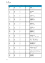
Name
Range
Step
Default
Description
Input value
2
-10
7
…10
7
0.001
1
The second input point in the mA output control curve.
Scaled mA
output
value 2
0.0000…24.0000mA 0.0001mA 0mA
The mA output value when the measured value is equal
to or greater than Input value 2.
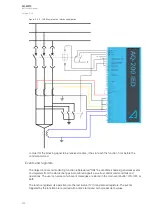
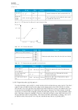
Figure. 5.4.4 - 150. Example of the effects of mA output channel settings.
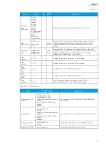
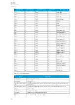
Table. 5.4.4 - 130. Hardware indications.
Name
Range Step
Description
Hardware in mA output channels 1...4 0: None
1: Slot A
2: Slot B
3: Slot C
4: Slot D
5: Slot E
6: Slot F
-
Indicates the option card slot where the mA output card is located.
Hardware in mA output channels 5...8
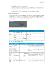
Table. 5.4.4 - 131. Measurement values reported by mA output cards.
Name
Range
Step
Description
mA in Channel 1
0.0000…24.0000mA 0.0001mA Displays the measured mA value of the selected input
channel.
mA in Channel 2
mA Out Channel Input
Magnitude now
-10
7
…10
7
0.001
Displays the input value of the selected mA output
channel at that moment.
mA Out Channel Outputs
now
0.0000…24.0000mA 0.0001mA Displays the output value of the selected mA output
channel at that moment.
5.4.5 Programmable control switch
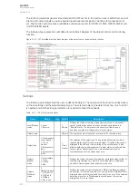
The programmable control switch is a control function that controls its binary output signal. This output
signal can be controlled locally from the relay's mimic (displayed as a box in the mimic) or remotely
from the RTU. The main purpose of programmable control switches is to block or enable function and
to change function properties by changing the setting group. However, this binary signal can also be
used for any number of other purposes, just like all other binary signals. Once a programmable control
switch has been activated or disabled, it remains in that state until given a new command to switch to
the opposite state (see the image below). The switch cannot be controlled by an auxiliary input, such
as digital inputs or logic signals; it can only be controlled locally (mimic) or remotely (RTU).
A
AQ
Q-M210
-M210
Instruction manual
Version: 2.04
243
Содержание AQ-M210
Страница 1: ...AQ M210 Motor protection IED Instruction manual ...
Страница 308: ...Figure 7 4 182 Example block scheme A AQ Q M210 M210 Instruction manual Version 2 04 307 ...
Страница 329: ...Figure 8 13 204 Panel cutout dimensions and device spacing A AQ Q M210 M210 Instruction manual Version 2 04 328 ...

