Name
Range
Step
Default
Protection
functions
Description
Nominal
starting
current
0.1…40.0xI
n
0.1xI
n
6.0xI
n
- Motor status
monitoring
- Machine
thermal
overload
protection
(Tm>; 49M)
- Motor start
monitoring
(Ist>; 48)
- Load jam
protection
(Im>; 51M)
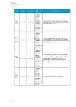
The motor's locked rotor current with the nominal
voltage. This setting is used for automatic curve
selection and calculation. Also, the nominal starting
capacity calculation is based on this value.
Nominal
starting
current A
0.1...5000A
0.1A
-
- Motor status
monitoring
- Machine
thermal
overload
protection
(Tm>; 49M)
- Motor start
monitoring
(Ist>; 48)
- Load jam
protection
(Im>; 51M)
The motor's locked rotor current in amperes.
Start detect
current
0.1…40.0xI
n
0.1xI
n
1.5xI
n
- Motor status
monitoring
- Motor start
monitoring
(Ist>; 48)
The motor starting current detection limit. When in
DOL or Star-Delta mode, this setting defines the motor
starting moment when the measured current exceeds
both the no-load current limit and the start detect
current limit within a ten-millisecond period. If the
current increases slower, it is not defined as a motor
start.
Start detect
current A
0.1...5000A
0.1A
-
- Motor status
monitoring
- Motor start
monitoring
(Ist>; 48)
The motor's starting current detection limit in amperes.
Min locked
rotor current
0.1…40.0xI
n
0.1xI
n
3.5xI
n
- Motor status
monitoring
- Machine
thermal
overload
protection
(Tm>; 49M)
- Motor start
monitoring
(Ist>; 48)
- Load jam
protection
(Im>; 51M)
The motor's minimum locked rotor current. This setting
defines the current limit for when this current is
exceeded while the automatic curve selection and the
control only short time constant (stall) are in use.
Min locked
rotor current A 0.1...5000A
0.1A
-
- Motor status
monitoring
- Machine
thermal
overload
protection
(Tm>; 49M)
- Motor start
monitoring
(Ist>; 48)
- Load jam
protection
(Im>; 51M)
The motor's minimum locked rotor current. This setting
defines the current limit for when this current is
exceeded while the automatic curve selection and the
control only short time constant (stall) are in use.
A
AQ
Q-M210
-M210
Instruction manual
Version: 2.04
128
Содержание AQ-M210
Страница 1: ...AQ M210 Motor protection IED Instruction manual ...
Страница 308: ...Figure 7 4 182 Example block scheme A AQ Q M210 M210 Instruction manual Version 2 04 307 ...
Страница 329: ...Figure 8 13 204 Panel cutout dimensions and device spacing A AQ Q M210 M210 Instruction manual Version 2 04 328 ...


