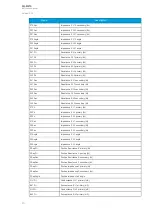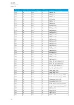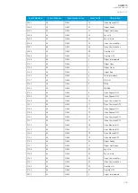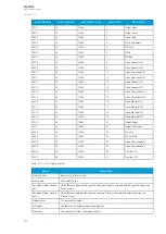
Event number
Event channel
Event block name
Event code
Description
4206
65
SGS
46
SG3 Active ON
4207
65
SGS
47
SG3 Active OFF
4208
65
SGS
48
SG4 Active ON
4209
65
SGS
49
SG4 Active OFF
4210
65
SGS
50
SG5 Active ON
4211
65
SGS
51
SG5 Active OFF
4212
65
SGS
52
SG6 Active ON
4213
65
SGS
53
SG6 Active OFF
4214
65
SGS
54
SG7 Active ON
4215
65
SGS
55
SG7 Active OFF
4216
65
SGS
56
SG8 Active ON
4217
65
SGS
57
SG8 Active OFF
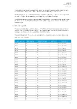
5.4.2 Object control and monitoring
The object control and monitoring function takes care of both for circuit breakers and disconnectors.
The monitoring and controlling are based on the statuses of the relay's configured digital inputs and
outputs. The number of controllable and monitored objects in each relay depends on the device type
and amount of digital inputs. One controllable object requires a minimum of two (2) output contacts.
The status monitoring of one monitored object usually requires two (2) digital inputs. Alternatively,
object status monitoring can be performed with a single digital input: the input's active state and its
zero state (switched to 1 with a NOT gate in the Logic editor).
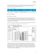
An object can be controlled manually or automatically. Manual control can be done by local control, or
by remote control. Local manual control can be done by relays front panel (HMI) or by external push
buttons connected to relays digital inputs. Manual remote control can be done through one of the
various communication protocols available (Modbus, IEC101/103/104 etc.). The function supports the
modes "Direct control" and "Select before execute" while controlled remotely. Automatic controlling can
be done with functions like auto-reclosing function (ANSI 79).
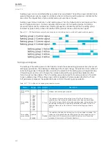
Object control consists of the following:
• control logic
• control monitor
• output handler.
In addition to these main parts, the user can add object-related circuit breaker failure protection
(CBFP; 50BF) and object wear monitoring in the object control block. These additional functions are
not included in the basic version of the object control block.
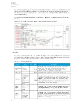
The main outputs of the function are the OBJECT OPEN and OBJECT CLOSE control signals.
Additionally, the function reports the monitored object's status and applied operations. The setting
parameters are static inputs for the function, which can only be changed by the user in the function's
setup phase.
The inputs for the function are the following:
• digital input status indications (the OPEN and CLOSE status signals)
• blockings (if applicable)
• the OBJECT READY and SYNCHROCHECK monitor signals (if applicable).
• Withdrawable cart IN and OUT status signals (if applicable).
A
AQ
Q-M210
-M210
Instruction manual
Version: 2.04
230
Содержание AQ-M210
Страница 1: ...AQ M210 Motor protection IED Instruction manual ...
Страница 308: ...Figure 7 4 182 Example block scheme A AQ Q M210 M210 Instruction manual Version 2 04 307 ...
Страница 329: ...Figure 8 13 204 Panel cutout dimensions and device spacing A AQ Q M210 M210 Instruction manual Version 2 04 328 ...


