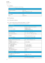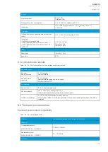
9.1.4 Display
Table. 9.1.4 - 207. Technical data for the HMI LCD display.
Dimensions and resolution
Number of dots/resolution
320 x 160
Size
84.78 × 49.90 mm (3.34 × 1.96 in)
Display
Type of display
LCD
Color
Monochrome
9.2 Functions
9.2.1 Protection functions
9.2.1.1 Non-directional overcurrent protection (I>; 50/51)
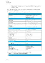
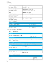
Table. 9.2.1.1 - 208. Technical data for the non-directional overcurrent function.
Measurement inputs
Current inputs
Phase current inputs: I
L1
(A), I
L2
(B), I
L3
(C)
Current input magnitudes
RMS phase currents
TRMS phase currents
Peak-to-peak phase currents
Pick-up
Pick-up current setting
0.10…50.00 × I
n
, setting step 0.01 × I
n
Inrush 2nd harmonic blocking
0.10…50.00 %I
fund
, setting step 0.01 %I
fund
Inaccuracy:
- Current
- 2
nd
harmonic blocking
±0.5 %I
set
or ±15 mA (0.10…4.0 × I
set
)
±1.0 %-unit of the 2
nd
harmonic setting
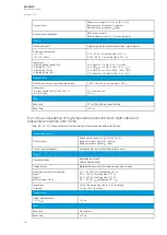
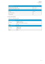
Operation time
Definite time function operating time setting
0.00…1800.00 s, setting step 0.005 s
Inaccuracy:
- Definite time: I
m
/I
set
ratio > 3
- Definite time: I
m
/I
set
ratio = 1.05…3
±1.0 % or ±20 ms
±1.0 % or ±30 ms
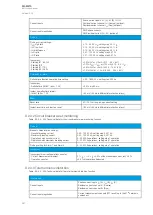
IDMT setting parameters:
- k Time dial setting for IDMT
- A IDMT constant
- B IDMT constant
- C IDMT constant
0.01…25.00, step 0.01
0…250.0000, step 0.0001
0…5.0000, step 0.0001
0…250.0000, step 0.0001
Inaccuracy:
- IDMT operating time
- IDMT minimum operating time
±1.5 % or ±20 ms
±20 ms
Retardation time (overshoot)
<30 ms
Instant operation time
Start time and instant operation time (trip):
- I
m
/I
set
ratio > 3
- I
m
/I
set
ratio = 1.05…3
<35 ms (typically 25 ms)
<50 ms
Reset
Reset ratio
97 % of the pick-up current setting
A
AQ
Q-M210
-M210
Instruction manual
Version: 2.04
337
Содержание AQ-M210
Страница 1: ...AQ M210 Motor protection IED Instruction manual ...
Страница 308: ...Figure 7 4 182 Example block scheme A AQ Q M210 M210 Instruction manual Version 2 04 307 ...
Страница 329: ...Figure 8 13 204 Panel cutout dimensions and device spacing A AQ Q M210 M210 Instruction manual Version 2 04 328 ...


