84
Timing, IRIG-B and Pulses
9.3.5
Programmable Pulse (PROG PULSE)
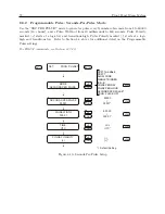
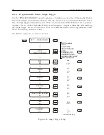
Model 1201B/C has a programmable pulse feature that may require some jumper and firmware
configuration. There are a number of available programmable pulse modes from which to choose
– see list below – that include setting the pulse width and time zone. For jumper configuration,
please see Section 5.2.4. For available modes and firmware configuration, see Section 8.8.
•
Seconds per pulse – set X number of seconds between pulses, 0 – 60,000
•
Pulse per hour – set number of seconds after each hour, 0 – 3599
•
Pulse per day – set hour, minute, second, fractional seconds
•
IRIG-B – set independent instance of unmodulated IRIG-B
•
Single trigger – set day, hour, minute, second, fractional seconds
•
Slow code – sets 2 seconds on the minute, 4 seconds on the hour, 6 seconds on the day
•
Pulse polarity – set positive or negative-going pulse
9.3.6
Programmable Pulse with Open Drain, Setup
For high-level switching on the main board, choose Open Drain from jumper settings described in
Section 5.2. Clocks can provide high-level switching at either Port 1 or or Port 3. Connect a voltage
of up to 200 volts and pull down a signal with the open drain 200 V FET. Make sure to connect
the FET with suitable protection against overvoltage transients and over current conditions. To
set timing output jumpers for programmable pulse with 200 V FET, see Table 5.1, or 5.4. Next,
you will need to configure the type of programmable pulse mode and timing through the utility
software (
??
), setup menus 8.8, or serial port 11.2.10.
9.3.7
Protecting the 200 V FET Connection
Open-drain outputs are not internally protected against over-current or overvoltage. Maximum
peak ratings are 100 mA and 200 V. External protections (current-limiting resistors, surge suppres-
sion diodes, snubbers, etc.) must be provided by the user, if required, to ensure that maximum
ratings are not exceeded even momentarily. Also, consult the data sheet of the TN0104 vertical
DMOS FET used in these models.
9.3.8
DCF77 Time Signal
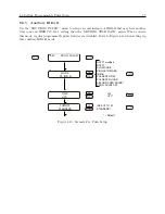
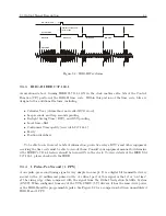
Model 1201B and 1201C can provide the DCF77 time signal as an output by choosing it from the
front panel within the PROG PULSE selections, or through the PROG PULSE selections in the
utility software. The DCF77 time signal occurs once per minute and provides the year, month, day
of week, calendar day, hour and minute, and various markers. DCF77 is a German long wave time
signal and standard-frequency radio station. The 1201B and 1201C can produce a DCF77 output
timing at 5 VTTL (CMOS) based on the radio signal protocol but synchronized to the GNSS.
Figure 9.3 shows the standard format with the missing 59th bit, whereas DCF77 Modified has the
59th bit set to 0.5 s
. See Section 8.8.8 for setting up the DCF77 timecode as an output.
Содержание 1201B
Страница 4: ...iv ...
Страница 153: ...B 7 Four Fiber Optic Outputs 135 Figure B 4 Jumper Locations ...
Страница 155: ...B 8 8 Channel High Drive IRIG B Amplifier 137 Figure B 5 8 High Drive Outputs Jumper Locations ...
Страница 171: ...B 10 Four Additional Outputs and Dry Contacts 25 50 Vdc 153 Figure B 7 Option Connector Signal Locations ...
Страница 222: ...Appendix E Statement of Compliance The following page is a statement of compliance that includes Model 1201B and 1201C ...

