9.4 Connecting the Outputs
85
Minute
Hour
Information content
provided by
third parties
Year
Month
R
A1
Z1
Z2
A2
S
1
2
4
8
10
20
40
P1
1
2
4
8
10
20
P2
1
2
4
8
10
20
1
2
4
Day of the
week
Calendar
Day
1
2
4
8
10
1
2
4
8
10
20
40
80
P2
P3
M
0
10
20
30
40
50
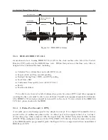
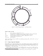
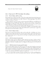
Figure 9.3: DCF77 Timing Diagram – see Marker Details
DCF77 Marker Details
M
minute marker (second marker No. 0): 0.1 s
R
second marker No. 15 indicates service request to the DCF77 signal generation system
A1
announcement of a forthcoming change from CET to CEST or vice versa
Z1, Z2
time zone indication: CET: Z1, 0.1 s, Z2 0.2 s; CEST: Z1 0.2 s, Z2 0.1 s
A2
announcement of a leap second, 0.2 s
P12, P2, P3
parity check bits
CET is Central European Time and CEST is Central European Summer Time. CET is UTC + 1:00, and
CEST is UTC + 2:00.
9.4
Connecting the Outputs
Model 1201B/C comes equipped with Phoenix-style, screw terminal connectors, which are compatible with
twisted pair cabling. To attach, strip the wires bare, DO NOT tin with solder, insert into the correct screw
terminal positions and tighten clockwise. To adapt coaxial cabling to the 1201B/C terminal connectors, use
a BNC Breakout
, or other similar adapter.
NOTE: If using a shielded, twisted-pair cable (like Belden 8760), connect the cable shield at only one
point and if possible at the clock. It has become best industry practice to ground time-code outputs from
1
Pomona Electrics, www.pomonaelectronics.com, (800) 444-6785, (425) 446-6010, part no. 4969 and 4970
Содержание 1201B
Страница 4: ...iv ...
Страница 153: ...B 7 Four Fiber Optic Outputs 135 Figure B 4 Jumper Locations ...
Страница 155: ...B 8 8 Channel High Drive IRIG B Amplifier 137 Figure B 5 8 High Drive Outputs Jumper Locations ...
Страница 171: ...B 10 Four Additional Outputs and Dry Contacts 25 50 Vdc 153 Figure B 7 Option Connector Signal Locations ...
Страница 222: ...Appendix E Statement of Compliance The following page is a statement of compliance that includes Model 1201B and 1201C ...

