32
Startup and Operation
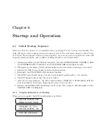
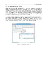
If the display indicates that the clock is not tracking satellites (00) make sure that the antenna
is mounted outside and in the clear from surrounding elements that may block the GNSS signals.
Also see Section 4.2 for information on troubleshooting antenna problems.
Note that the last screen indicates that the status is good and that the voltage and current are
correct for a GNSS antenna.
6.4.5
Position Display Modes
During startup the Model 1201B/C can run in one of two different modes that affect its operation.
These two modes are the normal mode and the demo mode. If the clock starts in the normal mode
and is acquiring satellites, the only position information available is the previous position, stored
in the clock’s memory. This position information reflects the location of the receiver as determined
by the last position while locked to at least four satellites. Displayed position will be based on
the most recent position fix. If the clock starts in the demo mode, it will not store any previous
position information and essentially start over from scratch.
Synchronization to a minimum of four satellites is necessary for precise determination of longi-
tude, latitude, and elevation. When meeting this minimum satellite lock requirement, its position
will accurately correspond to the present antenna location.
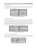
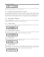
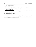
Longitude Display
Displays the antenna longitude in degrees, minutes, seconds and fractional seconds, East or West.
ANTENNA LONGITUDE
XXX
◦
XX’ XX.XXX" W
*
Where:
*
W
= WEST, or
E
= EAST
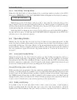
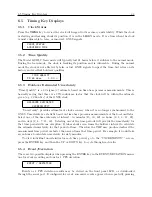
Latitude Display
Displays the antenna latitude in degrees, minutes, seconds and fractional seconds, North or South.
ANTENNA LATITUDE
XX
◦
XX’ XX.XXX" N
*
Where:
*
N
= NORTH, or
S
= SOUTH
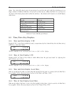
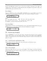
Elevation Display
Displays the antenna elevation in meters and fractional meters referenced to the WGS-84 datum.
ANTENNA ELEVATION
XXXXX.XX m WGS-84
Содержание 1201B
Страница 4: ...iv ...
Страница 153: ...B 7 Four Fiber Optic Outputs 135 Figure B 4 Jumper Locations ...
Страница 155: ...B 8 8 Channel High Drive IRIG B Amplifier 137 Figure B 5 8 High Drive Outputs Jumper Locations ...
Страница 171: ...B 10 Four Additional Outputs and Dry Contacts 25 50 Vdc 153 Figure B 7 Option Connector Signal Locations ...
Страница 222: ...Appendix E Statement of Compliance The following page is a statement of compliance that includes Model 1201B and 1201C ...

