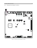
5.2 Setting Mainboard Jumpers
25
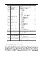
list each separate input/output function and their respective jumpers.
5.2.3
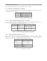
IRIG-B Unmodulated, 5 V Outputs
A 5 V
T T L
unmodulated IRIG-B signal may be configured at either Port 1 or Port 3. For each port
two jumpers need to be verified.
Port Number
Required Jumper Positions
1
JMP6 = C and JMP7 = A
3
JMP8 = C and JMP9 = A
Table 5.2: Unmodulated IRIG-B Jumper Table
5.2.4
1 PPS and Programmable Pulse, 5 V Outputs
A 5 V
T T L
pulse per second or programmable pulse output may be configured at either Port 1 or
Port 3. Two jumpers need to be verified for each port.
Port Number
Signal
Required Jumper Positions
1
1 PPS
JMP6 = A and JMP7 = A
Programmable Pulse
JMP6 = B and JMP7 = A
3
1 PPS
JMP8 = A and JMP9 = A
Programmable Pulse
JMP8 = B and JMP9 = A
Table 5.3: 1 PPS and Programmable Pulse Jumper Table
5.2.5
Analog and Digital Outputs: Port 2
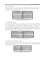
Port 2 can be configured to produce a modulated IRIG-B signal or as an event input by jumper
selection. Port 2 may also source digital signals like Ports 1 and 3, however setting jumpers are
different from Ports 1 and 3. See Section 5.2.6 for additional settings.
Port 2 Function
Required Jumper Positions
1 PPS
JMP12 = A and JMP13 = A
Programmable Pulse
JMP12 = A and JMP13 = B
Unmodulated IRIG-B
JMP12 = A and JMP13 = C
Modulated IRIG-B
JMP12 = B
Event Input
JMP12 = C
Table 5.4: Analog Signal Jumper Table
Содержание 1201B
Страница 4: ...iv ...
Страница 153: ...B 7 Four Fiber Optic Outputs 135 Figure B 4 Jumper Locations ...
Страница 155: ...B 8 8 Channel High Drive IRIG B Amplifier 137 Figure B 5 8 High Drive Outputs Jumper Locations ...
Страница 171: ...B 10 Four Additional Outputs and Dry Contacts 25 50 Vdc 153 Figure B 7 Option Connector Signal Locations ...
Страница 222: ...Appendix E Statement of Compliance The following page is a statement of compliance that includes Model 1201B and 1201C ...

