Chapter 6
Startup and Operation
6.1
Initial Startup Sequence
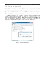
Make sure that the chassis cover is installed before powering ON any of these clock models. The
clock will begin a start sequence when you connect power to the clock inlet connector, either Power
A or Power B (if equipped with two power supplies). As soon as power is applied, the clock will
begin the startup sequence and a number of things should occur as listed below:
1. Annunciator LED’s should flash momentarily, then the OPERATE LED, POWER A LED
(and POWER B LED, if installed) and UNLOCKED LED should light steadily.
2. The liquid crystal display (LCD) should display several introductory messages (see below).
3. Initially, the SPDT relay should be in the faulted position.
4. Eventually, the UNLOCKED LED should extinguish.
5. The SPDT relay should change to Locked (non-faulted) position after a few minutes.
6. The LCD should indicate that the clock is locked.
7. After the startup messages, the LCD should indicate TIME NOT AVAILABLE until the
clock is stabilized, then begin displaying the time of day and date.
8. Initially, the LEARN LED should light for 24 hours, after which it will extinguish and the
NORMAL LED will illuminate.
6.1.1
Display Indication at Startup
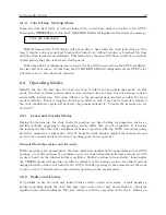
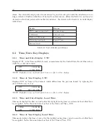
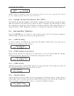
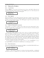
When power is applied, the LCD should indicate as follows:
ARBITER SYSTEMS GNSS
MODEL 1201B/C CLOCK
COPYRIGHT (C) 2014
ARBITER SYSTEMS, INC.
TIME NOT AVAILABLE
Содержание 1201B
Страница 4: ...iv ...
Страница 153: ...B 7 Four Fiber Optic Outputs 135 Figure B 4 Jumper Locations ...
Страница 155: ...B 8 8 Channel High Drive IRIG B Amplifier 137 Figure B 5 8 High Drive Outputs Jumper Locations ...
Страница 171: ...B 10 Four Additional Outputs and Dry Contacts 25 50 Vdc 153 Figure B 7 Option Connector Signal Locations ...
Страница 222: ...Appendix E Statement of Compliance The following page is a statement of compliance that includes Model 1201B and 1201C ...

