122
Technical Specifications and Operating Parameters
12.9
Power Inlet Specifications
The Model 1201B/C may have either one or two user-specified internal power supplies. Additionally, the
antenna receives power through the antenna cable connected to the Type F connector on the rear panel.
Universal:
85 Vac to 264 Vac, 47 Hz to 440 Hz,
<
20 VA, or 110 Vdc to 350 Vdc,
<
30 W typical, with
three-position Terminal Power Strip and Surge-Withstand Capability.
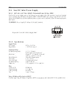
Low DC:
22 Vdc to 67 Vdc (dc only),
<
30 W typical. Uses a three-position terminal strip and Surge-
Withstand Capability.
12.9.1
Power Inlet Connector
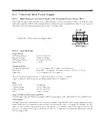
Uses a 3-pole terminal strip power inlet with Surge-Withstand Capability (see Figure 2.4 and 2.5).
12.9.2
Electro-Magnetic Interference (EMI)
Conducted Emissions:
power supplies (Options A01/B01 and A02/B02) comply with FCC 20780, Class
A and VDE 0871/6.78, Class A
Surge Withstand Capability (SWC)
, power inlet (Options A01/B01 and A02/B02) designed to meet
ANSI/IEEE C37.90-1 and IEC 801-4.
Содержание 1201B
Страница 4: ...iv ...
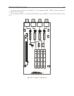
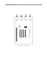
Страница 153: ...B 7 Four Fiber Optic Outputs 135 Figure B 4 Jumper Locations ...
Страница 155: ...B 8 8 Channel High Drive IRIG B Amplifier 137 Figure B 5 8 High Drive Outputs Jumper Locations ...
Страница 171: ...B 10 Four Additional Outputs and Dry Contacts 25 50 Vdc 153 Figure B 7 Option Connector Signal Locations ...
Страница 222: ...Appendix E Statement of Compliance The following page is a statement of compliance that includes Model 1201B and 1201C ...


