


Upgrading TPI/4 Firmware
51
NXP-TPI/4 NetLinx Touch Panel Interface
Upgrading the TP4 Input Cards via an IP Address
The v 2.XX firmware KIT file (available at www.amx.com) upgrades any connected TP4 Input cards. If
there is both a TP4-RGB and TP4-VID card in a TPI/4, then the KIT file updates the firmware on both
cards. Note that if you later add additional cards, you should follow these update procedures again. The
following accessory devices are firmware upgradeable:
TP4-RGB TPI/4 Input Card (
FG2275-20
)
TP4-VID TPI/4 Input Card (
FG2275-10
)
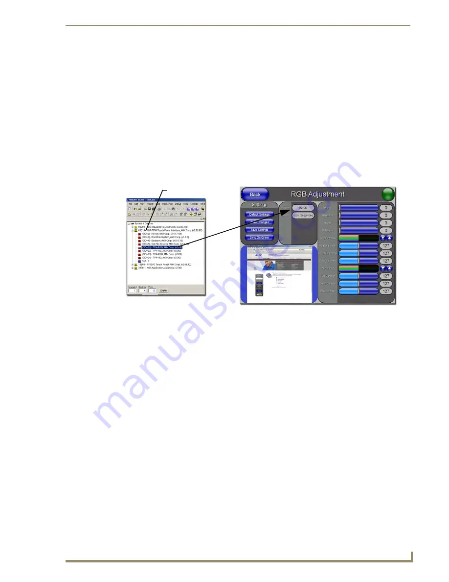
These devices are not given unique device numbers which would ordinarily appear within the Online
Tree tab of NetLinx Studio. They appear as part of device which they are connected
(TP4-RGB and TP4-VID) as seen below in FIG. 36.
Each card has its own Adjustment page: the TP4-
RGB has the RGB Adjustment page (seen below) while the TP4-VID card has the Video Adjustment
page.
The only way to upgrade the firmware of an accessory item is to send the accessory’s firmware through a
target G4 device (such as the TPI/4). Its the TPI/4’s device number which is entered within the
Send to
NetLinx Device transfer
dialog in Studio.
Step 1: Prepare the cards for firmware transfer
Before beginning this section:
Refer to the
Removing TP4 Input Cards
section on page 15 for installation procedures.
Verify your cards are properly installed and that all connectors are securely fastened.
1.
Identify the Device number of the target TPI/4 being used for firmware routing to the accessories.
2.
Complete the instructions for configuring the NetLinx Master for IP communication found in the
Step 1: Prepare the Master for communication through an IP
section on page 47.
3.
Press the front panel SETUP button to open the Setup page.
4.
Confirm the current firmware version on the cards by pressing the
Video Adjustment
button and
then the corresponding
Slot #
button of the target TP4 card. This action opens the corresponding
Adjustment pages (FIG. 37). The slots for these cards are labeled at the rear of the unit.
FIG. 36
Location of Firmware version information within NetLinx Studio and Firmware page
TP4-RGB
firmware
Target TPI/4 Device #
NetLinx Studio Online Tree tab
Accessory’s corresponding firmware page
Содержание NetLinx NXP-TPI/4
Страница 38: ...TPI 4 and Panel Interface Setup 32 NXP TPI 4 NetLinx Touch Panel Interface...
Страница 60: ...Upgrading TPI 4 Firmware 54 NXP TPI 4 NetLinx Touch Panel Interface...
Страница 138: ...Troubleshooting 132 NXP TPI 4 NetLinx Touch Panel Interface...
Страница 147: ...Appendix 141 NXP TPI 4 NetLinx Touch Panel Interface...


