Control Panel Operation
58
Epica DGX 32 Instruction Manual
Local Preset
Selecting Local Preset accesses the list of local presets that can be executed (see page 65). Local Preset
will only appear as an option on the Function menu if local presets have been defined in XNConnect for
the selected virtual matrix.
Epica DGX 32 Control Panel operation consists of the following four basic tasks:
Choosing a mode, submenu, or list:
press the Function Key to access the Function menu.
Use the Control Dial and Select Key to choose the desired mode, submenu, list, or list item.
Selecting Inputs or outputs:
press the corresponding Input or Output Key. Selected keys will
change color or flash, depending on the routing state.
Selecting values for fields:
use the Control Dial and Select Key (e.g., virtual matrices or
global presets).
Executing a command:
press the Take Key.
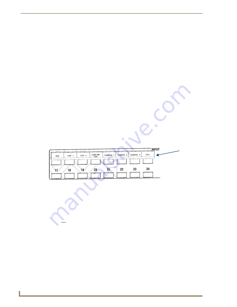
Labeling Input and Output Keys
Each Epica DGX 32 system ships with a kit for custom labeling. Additional kits may be ordered
separately. The Control Panel Label Kit (KA1056-01) includes:
Perforated card stock sheets
– Print, separate labels, and slide into holders.
Label holders
– Attach to the front panel above each row of Input and Output Keys.
LCD Function menu label
– Shows entire LCD menu structure (see Note on previous page).
The label template (an .xlt template formatted in Microsoft Excel) for labeling the input and output keys
is included on the
AMX AutoPatch CD
and is available at
www.amx.com
.
Tip: When the labels are ready to print, we recommend printing a sample on plain paper first.
To create and install labels for Input and Output Keys:
1.
From the
AMX AutoPatch CD
, launch the Label Form Spreadsheet.xlt file.
2.
Type the labels in the pre-formatted cells on the template according to the instructions in the
template (if desired, use standard Excel editing tools to alter font size, spacing, color, etc.).
Do not modify the cell size.
3.
Save the file for future use (recommended).
4.
Print the labels on the perforated sheets provided, using any standard laser printer.
5.
Trim off the excess label insert material where indicated.
6.
Separate the label strips at their perforations (bend both ways first).
7.
Slide the first label strip into a plastic label holder (position with open edge of holder up).
8.
Peel the adhesive backing off the label holder and press the holder firmly onto the control panel
above the appropriate Input or Output Keys. The silk screened labels on the front panel will aid in
label holder alignment.
9.
Repeat Steps 7 and 8 for the remaining labels.
FIG. 33
Customize labels to designate sources and destinations
Slide label into
holder before
attaching to
Control Panel
Содержание Epica DGX 32
Страница 1: ...Instruction Manual AutoPatch Matrix Switchers Epica DGX 32 Distribution Matrix Release 3 19 2010 ...
Страница 6: ...Contents iv Epica DGX 32 Instruction Manual ...
Страница 12: ...Notices 6 Epica DGX 32 Instruction Manual ...
Страница 50: ...Installation and Setup 44 Epica DGX 32 Instruction Manual ...
Страница 56: ...Epica DGX 32 SC Optical Boards 50 Epica DGX 32 Instruction Manual ...
Страница 60: ...Epica DGX 32 DVI Boards 54 Epica DGX 32 Instruction Manual ...
Страница 98: ...NXB AP 1000 Interface Initial Setup by Network Admin 92 Epica DGX 32 Instruction Manual ...
Страница 102: ...NXB AP 1000 Interface Controlling the Epica DGX 32 96 Epica DGX 32 Instruction Manual ...
Страница 108: ...NXB AP 1000 Interface Additional Info for Network Admin 102 Epica DGX 32 Instruction Manual ...
Страница 114: ...Appendix A EDID Programmer 108 Epica DGX 32 Instruction Manual ...
Страница 126: ...Appendix B Managing Configuration Files 120 Epica DGX 32 Instruction Manual ...


