31
RS1500000 Rev. 0
Disassembly Procedures
To avoid risk of electrical shock, personal injury, or
death, disconnect power to unit before following any
disassembly procedures.
WARNING
!
15.Straighten heat exchanger tubing to pass through the
opening in the cabinet back.
16.Pull entire assembly out through the front. Position to
allow detachment of heat exchanger.
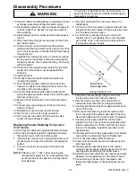
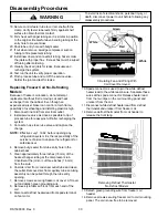
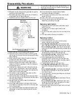
17.Unsolder suction and capillary tube from the coil.
Protect
these joints
Unsolder
these joints
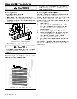
Heat Exchanger To Freezer Coil Joints
No-Defrost Models
18.Remove freezer coil and replace with new coil.
19.Clean and connect tubes and silver solder the joints
with proper flux. Excess flux must be wiped off tubing
after soldering.
20.Work heat exchanger tubing through rear opening,
careful not to tear rubber sleeve.
21.Position freezer coil and install mounting screws.
Replace styrofoam air blocks at the upper ends of
freezer coil. This is necessary in order to channel air
flow through the coil.
22.Carefully form tubing and route in the same manner
as the original. Use extreme caution when bending
tubing at the entrance hole to prevent a possible kink.
Pack entry hole with butyl sealer.
23.If cut when removed, swedge compressor suction
tube to reconnect suction tubing.
24.Clean all the tubes. Install new drier and silver solder
the joints with proper flux. Excess flux must be wiped
off tubing after soldering.
25.Visually check the joints for leaks. Evacuate and
recharge the system.
26.Lace white heater leads to both ends of the freezer
coil. Fasten wire leading to fan motor to the two clips
on the mount-panel.
27.Join white defrost heater lead and white lead-in wire
with spade connector and attach spade terminal on
fan motor.
28.Connect defrost thermostat lead and fasten
thermostat to freezer coil header.
29.Connect green grounding wire to fan motor and to
freezer coil cover.
30.Test run the unit to verify proper operation.
31.Pinch process tube and cut off the service valve.
Solder the joint and test for leaks.
Replacing Light Switch
1. Unplug line cord from electrical outlet and pry light
switch from liner.
2. Pull lead wires out far enough to disconnect
connectors.
3. Connect new switch, plug in line cord, and check the
light.
4. Push new switch and wiring into position.
Replacing Control
1. Unplug the power cord.
2. Pull control knob off, remove control mounting
screws, and disconnect all wires.
3.
On refrigerated shelf models
, remove feeler tube
from underside of shelf front by loosening the clamp.
On no defrosting models
, disconnect control feeler
tube cover from the liner side by pulling straight out at
its center.
4.
On refrigerated shelf models
, securely tape a piece
of heavy string to the end of the feeler tube.
On no defrosting models
, observe feeler tube is
coiled behind the cover, then straighten it.
5. Pull complete assembly out of cabinet, (on
refrigerated shelf models, string end should follow
through the hole in the liner side so it can be used to
pull replacement back through.
6. Transfer plastic sleeve to new feeler tube.
7.
On refrigerated shelf models
, tape string to new
feeler tube. Pull tube through the hole in the liner
side.
On no defrosting models
, work feeler tube through
the opening and reshape it so it will not contact the
inner side or cover.
8. Connect all wires, including grounding wire, and push
control into position.
9. Reinstall mounting screws.
10.
On refrigerated shelf models
, secure feeler tube to
underside of shelf front.
On no defrosting models
, attach feeler tube cover
by bowing it out at the center until tabs on the cover
can be fitted into slots in the liner.
11. Reinstall control knob. Plug in power cord and check
freezer operation.

