Chapter 2: Virtual Chassis Stacking
50
Stack Trunks
The switches of a stack are connected with a physical network link called
a stack trunk. Here are general trunk guidelines:
The ports of a stack trunk can be 10Gbps, 40Gbps, or 100Gbps.
The switch does not have default trunk ports.
A stack can have only one trunk, but, as explained in this section, a
trunk can have more than one physical link.
You designate trunk ports with the STACKPORT command in the
AlliedWare Plus operating system.
Once you have designated ports as trunk ports, you cannot view or
change their parameter settings.
The fiber optic transceivers or direct attach cables of a trunk must
be from Allied Telesis. Transceivers or cables from other network
equipment providers might not perform properly in stack trunks.
For a list of supported transceivers, refer to the Allied Telesis web
site.
A stack of AT-x950-28XSQ Switches cannot have other stacking
products, such as x600 Series switches.
A trunk must have a minimum of two physical links.The more links
in a trunk the greater its bandwidth and resiliency.
If the trunk fails, the two switches revert to stand-alone devices.
You use ports or transceiver slots from these groups to build a stack trunk:
“10Gbps SFP+ Transceiver Slots,” next
“40/100Gbps Transceiver Slots” on page 53
“Optional XEM2 Line Cards” on page 55
10Gbps SFP+
Transceiver Slots
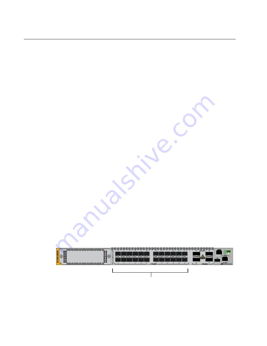
Here are the guidelines for stack trunks of 10Gbps transceiver slots,
identified in Figure 19:
Figure 19. Base 10Gbps Transceiver Slots
A stack trunk can have from two to eight links.
Base 10Gbps SFP+
Transceivers Slots
Содержание AT-x950-28XSQ
Страница 8: ...Contents 8 ...
Страница 12: ...Tables 12 ...
Страница 16: ...Preface 16 ...
Страница 62: ...Chapter 2 Virtual Chassis Stacking 62 ...
Страница 80: ...Chapter 3 Beginning the Installation 80 ...
Страница 90: ...Chapter 4 Installing Power Supplies and Optional XEM2 Line Card 90 ...
Страница 102: ...Chapter 6 Installing the Switch in an Equipment Rack 102 ...
Страница 106: ...Chapter 7 Installing the Switch on a Wall 106 Figure 67 Minimum Wall Area Dimensions with the Front Panel on the Right ...
Страница 118: ...Chapter 7 Installing the Switch on a Wall 118 ...
Страница 146: ...Chapter 8 Configuring Switches for Stacking 146 ...
Страница 158: ...Chapter 9 Cabling the Networking Ports 158 ...
Страница 164: ...Chapter 10 Replacing Modules 164 Figure 94 Tightening the Two Screws on the Line Card Blank Panel ...
Страница 169: ...AT x950 28XSQ Switch and VCStack Installation Guide 169 Figure 100 Installing the Blank Power Supply Cover ...
Страница 180: ...Chapter 11 Troubleshooting 180 ...
Страница 190: ...Appendix A Technical Specifications 190 ...


