background image

27

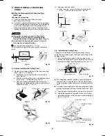
3-19.  Suspending the Indoor Unit

Depending on the ceiling type:

 • 


Insert suspension bolts (Fig. 3-58) 
or

 • 


Use existing ceiling supports or construct a suitable 
support (Fig. 3-59).

Insert

Hole-in-anchor
Hole-in-plug

Concrete

Suspension bolt (M10 or 3/8")
(field supply)

Fig. 3-58

Ceiling support

Ceiling tiles

Fig. 3-59

WARNING

It is important that you use extreme care in supporting 
the indoor unit inside the ceiling. Ensure that the ceiling 
is strong enough to support the weight of the unit. Before 
hanging the unit, test the strength of each attached 
suspension bolt.

(1)  When placing the unit inside the ceiling, determine the 

pitch of the suspension bolts referring to the dimensional 
data as shown in Fig. 3-56 and Table 3-4. 
Tubing must be laid and connected inside the ceiling when 
suspending the unit. If the ceiling is already constructed, 
lay the tubing into position for connection to the unit before 
placing the unit inside the ceiling.

(2)  Screw in the suspension bolts allowing them to protrude 

from the ceiling (Fig. 3-58). (Cut the ceiling material, if 
necessary.)

(3)  Thread the 3 hexagonal nuts and 2 washers (field supply) 

onto each of the 4 suspension bolts (Figs. 3-60 and 3-61). 
Use 1 nut and 1 washer for the upper part, and 2 nuts and 
1 washer for the lower part, so that the unit will not fall off 
the suspension lugs.

Nuts and washers
(use for upper and lower)

Suspension lug

Double nuts

Suspension bolt

Notch

Fig. 3-60

Suspension bolt

Double nuts

Hexagonal nut

Fig. 3-61

  This shows an example of installation.

Air outlet duct

Air-outlet grille

Ceiling material

Indoor unit

Air-intake 
grille

Suspension 
bolt

Bolt anchor

Air-intake 
duct

Fig. 3-62

Airwell̲PAC-i̲eng.indb   27

Airwell̲PAC-i̲eng.indb   27

2009/07/09   16:13:26

2009/07/09   16:13:26

Содержание OU-PSINV-25HR

Страница 1: ...ncealed Duct IU PSINV D12R IU PSINV D16R IU PSINV D18R IU PSINV D25R IU PSINV D36R IU PSINV D48R IU PSINV D60R Outdoor Units OU Outdoor Units OU PSINV 25HR OU PSINV 36HR OU PSINV 48HR OU PSINV 60H Refrigerant R410A is used in the outdoor units Optional Controllers RC Remote Controller NRCT FLR Wireless Remote Controller For 4WK type AWAC RCIRA FL Wireless Remote Controller For C type AWAC RCIRD FL...

Страница 2: ...htly Loose wiring may cause over heating at connection points and a possible fire hazard When Transporting Be careful when picking up and moving the indoor and out door units Get a partner to help and bend your knees when lifting to reduce strain on your back Sharp edges or thin alumi num fins on the air conditioner can cut your fingers When Installing In a Room Properly insulate any tubing run in...

Страница 3: ...r However since it contains more than air it poses the risk of suffocation if its density should rise excessively Suffocation from leakage of refrigerant is almost non existent With the recent increase in the number of high density buildings however the installation of multi air conditioner systems is on the increase because of the need for effective use of floor space individual control and energ...

Страница 4: ...ormance and cause defects of the unit 2 2 Since refrigerant composition changes and performance decreases when gas leaks collect the remaining refrigerant and recharge the required total amount of new refrigerant after fixing the leak 3 Different tools required 3 1 Tool specifications have been changed due to the characteristics of R410A Some tools for R22 and R407C type refrigerant systems cannot...

Страница 5: ...or Unit 3 10 Preparing the Tubing 3 11 Shaping the Tubing 3 12 Installing the Drain Hose Ceiling Mounted Type C Type 22 3 13 Required Minimum Space for Installation and Service 3 14 Suspending the Indoor Unit 3 15 Duct for Fresh Air 3 16 Shaping the Tubing 3 17 Installing the Drain Pipe Concealed Duct Type D Type 26 3 18 Required Minimum Space for Installation and Service 3 19 Suspending the Indoo...

Страница 6: ... Preparation for Test Run 10 13 Test Run 10 14 Precautions 10 15 Table of Self Diagnostic Functions and Corrections 10 16 System Control 4WK C D Types for Link Wiring 57 10 17 Caution 10 18 Test Run Procedure 10 19 Items to Check Before the Test Run 10 20 Test Run Using the Remote Controller 10 21 Table of Self Diagnostic Functions and Corrections 4WK C D Types 10 22 Automatic Address Setting HW T...

Страница 7: ...s of the insulation should be not less than 8 mm 3 Use insulated copper wire for field wiring Wire size varies with the total length of wiring Refer to 5 ELECTRICAL WIRING for details CAUTION Check local electrical codes and regulations before obtaining wire Also check any specified instructions or limitations 1 4 Additional Materials Required for Installation 1 Refrigeration armored tape 2 Insula...

Страница 8: ...unit PVC pipe joints Hose band 2 For drain hose connection Table 1 4 Concealed Duct Part Name Figure Q ty Remarks Washer 8 For suspending indoor unit from ceiling Flare insulator 2 For gas and liquid tubes Insulating tape 2 For gas and liquid tubes flare nuts Dain insulator 1 For drain hose joint Hose band 1 For securing drain hose Packing 1 For drain joint Drain hose 1 Sealing putty 1 For sealing...

Страница 9: ...nt indoor unit L L 1 L 2 L 1 L 2 L 3 L L1 1 L L1 2 L L2 3 L L2 4 50 Maximum distribution tubing length Maximum length following the first branch point No 1 distribution 1 2 1 2 3 L1 1 L1 2 L2 3 L2 4 15 Maximum branch tubing length Difference between the maximum length and minimum length in tubing following the first branch point 1 2 1 2 1 2 3 1 2 1 3 2 3 Max L2 4 Min L1 1 L2 4 L1 1 10 Maximum diff...

Страница 10: ...he size and length of the liquid tubing Amount of additional refrigerant charge g Do not remove refrigerant from the system even if the result of the calculation is negative Additional refrigerant amount g Additional refrigerant for main tubing g Additional refrigerant for distribution tubing g Outdoor unit charge less refrigerant amount g 40X a 40X b 20X c 1200 25 60 type Use with the current ref...

Страница 11: ...121 5 135 5 10 15 20 25 30 35 40 45 50 m3 m2 20 30 40 Min indoor floor area when the ceiling is 2 7 m high Range below the density limit of 0 3 kg m3 Countermeasures not needed Range above the density limit of 0 3 kg m3 Countermeasures needed Min indoor volume Total amount of refrigerant Kg CAUTION Pay special attention to any location such as a basement or recessed area etc where leaked refrigera...

Страница 12: ...ical installation directed upward or downward Nitrogen gas replacement required for tube brazing If nitrogen replacement is not done when brazing is performed on the indoor and outdoor unit refrigerant tubing oxide scale will occur This scale will clog the solenoid valves strainers and other parts leading to malfunction Therefore be sure to replace the air in the tubing with nitrogen when performi...

Страница 13: ...s which may affect the performance of the unit locations where external air may enter the room directly This may cause condensation on the air discharge ports causing them to spray or drip water locations where the remote controller will be splashed with water or affected by dampness or humidity installing the remote controller behind curtains or furniture locations where high frequency emissions ...

Страница 14: ... 1 cm Outlet side More than 100 cm More than 1 cm Fig 2 5 1 A B Obstruction above unit Air direction chamber field supply Obstruction on inlet side ground Inlet side More than 20 cm Fig 2 6 NOTE Concerning inlet side distance C Fig 2 5 The minimum for distance C is 15 cm if there are no obstructions on the outlet side wall 1 side and 2 or 4 is not present In all other cases the minimum for distanc...

Страница 15: ...snow proof ducting a The outdoor fan may not run and damage of the unit may be caused b There may be no airflow c The tubing may freeze and burst d The condenser pressure may drop because of strong wind and the indoor unit may freeze Fig 2 9 In regions with significant snowfall the outdoor unit should be provided with a platform and snow proof duct 2 5 Precautions for Installation in Heavy Snow Ar...

Страница 16: ...the supplied full scale installation diagram The diagram and table Fig 3 3 and Table 3 2 show the relationship between the positions of the suspension fitting the unit and the panel E A B C D 35 Unit mm Drain outlet other side VP25 Refrigerant tubing joint narrow side Refrigerant tubing joint wide side Suspension lug Fig 3 3 Table 3 2 Unit mm Length Type A B C D E 12 16 18 25 113 173 256 210 88 36...

Страница 17: ...f 2 The pipe cannot be removed when maintenance is needed Do not bend the supplied drain hose 90 or more The hose may slip off Align the hose bands with the end of the hose Tighten the hose band firmly Make sure that the bead is not covered by the hose band Fig 3 6 2 After checking the drainage wrap the supplied packing and drain pipe insulator around the pipe Fig 3 7 Drain insulator supplied Viny...

Страница 18: ...it during transportation 2 Press up on the rear panel at the 2 locations shown by the arrows and remove the rear panel Fig 3 13 Screws used during transportation Remove the rear panel Press Fig 3 13 NOTE Tubing can be extended in 4 directions Select the direction which will provide the shortest run to the outdoor unit Fig 3 14 Left tubing Right rear tubing recommended Left rear tubing Right tubing...

Страница 19: ... the panel or drill 5 mm dia holes in the panel over the stud locations and then mount the rear panel Fig 3 19 2 Check with a tape measure or carpenter s level This is important so that the unit is correctly installed Fig 3 20 Fig 3 20 3 Make sure the panel is flush against the wall Any space between the wall and unit will cause noise and vibration b If the Wall is Brick Concrete or Similar Drill ...

Страница 20: ... on the air outlet to hold it in place and press the lower part of the indoor unit until a click sound is heard and the indoor unit is securely fastened to the attachment tabs on the lower side of the rear panel Fig 3 27 Press Fig 3 27 Raising the clamp to lift up the indoor unit will facilitate this work Fig 3 28 Clamp Fig 3 28 To remove the indoor unit press up on the 2 locations marks on the lo...

Страница 21: ...s securely mounted on the rear panel 3 12 Installing the Drain Hose a The drain hose should be slanted downward to the outside Fig 3 32 Indoor unit Slant Refrigerant tubing Fig 3 32 b Never allow water traps to be formed in the course of the hose c If the drain hose will run in the room insulate the hose so that chilled condensation will not damage furniture or floors Foamed polyethylene or its eq...

Страница 22: ... 84 32 32 60 171 347 125 72 85 106 90 262 1 1 2 3 Left side drain hose outlet port Side panel Remote controller wiring inlet port ø30 knock out Top outlet port Power inlet port ø40 knock out Knock out Right side drain hose outlet port Side panel Position of plate inside side panel 3 Remote controller wiring inlet port ø30 rubber grommet on right side only Rear outlet port Outside air intake duct c...

Страница 23: ...nt 1 washer and 2 hexagonal nuts on each suspension bolt Fig 3 45 Suspension bolt field supply Ceiling surface Unit Washer supplied Double nut field supply Fixture Fig 3 43 4 Wall and ceiling side opening position 90 145 135 125 155 90 Figure shows view from front Figure shows view from top ø100 wall side opening for left side drain hose ø100 wall side opening ø100 ceiling opening Wall ø100 ceilin...

Страница 24: ...e routed out together use a box cutter or similar tool to cut out the part of the rear cover indicated by the marked area Fig 3 52 to match the positions of the tubes Then draw out the tubing Rear cover Fig 3 52 Suspension bolt field supply Washer field supply Unit Washer supplied Double nut field supply Fig 3 44 Washer supplied Suspension bolt Approx 25 mm Ceiling surface Nut field supply Fig 3 4...

Страница 25: ... the left side refer to Fig 3 51 and follow the procedure above to install the hose Reattach the rubber stopper removed earlier onto the right side The rubber stopper can be inserted easily by using a screwdriver or similar tool to press the stopper into the drain port on the main unit Press the stopper into the main unit drain port as far as it will go Rubber stopper Screwdriver Drain port CAUTIO...

Страница 26: ...er of duct flanges 2 3 4 It is recommended that space be provided 450 450 mm for checking and servicing the electrical system The detailed dimensions of the indoor unit is shown in Fig 3 57 and Table 3 4 Table 3 4 Unit mm Dimension Type A B C D E F G H I J K No of holes L M 12 16 18 662 600 200 3 700 780 290 262 680 715 180 340 8 12 25 962 900 180 5 1 000 1 080 290 272 980 1 015 130 245 245 1 250 ...

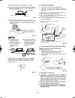
Страница 27: ...Tubing must be laid and connected inside the ceiling when suspending the unit If the ceiling is already constructed lay the tubing into position for connection to the unit before placing the unit inside the ceiling 2 Screw in the suspension bolts allowing them to protrude from the ceiling Fig 3 58 Cut the ceiling material if necessary 3 Thread the 3 hexagonal nuts and 2 washers field supply onto e...

Страница 28: ...the pipe then secure it with the supplied vinyl clamps Fig 3 64 Drain insulator supplied Vinyl clamps Fig 3 64 NOTE Make sure the drain pipe has a downward gradient 1 100 or more and that there are no water traps CAUTION Do not install an air bleeder as this may cause water to spray from the drain pipe outlet Fig 3 65 1 Prohibited Air bleeder Fig 3 65 1 If it is necessary to increase the height of...

Страница 29: ...ent box Fan motor Booster cable At shipment Booster cable installed Fan motor socket Booster cable Fig 3 67 5 Place the cable neatly in the box and reinstall the cover plate Indoor Fan Performance 5 0 50 100 0 5 10 15 150 10 HT H M L 15 0 50 0 5 10 15 150 10 HT M L 100 H 12 Type 16 18 Type AirFlow m 3 minute External Static Pressure External Static Pressure Pa Pa L i m i t l i n e L im it li n e L...

Страница 30: ...gradient against horizontal Fig 3 69 3 24 Required Minimum Space for Installation and Service If the ceiling tiles cannot be removed provide the opening holes on the lower side of the indoor unit for removing the unit in order to maintain and clean the drain pan and heat exchanger or provide a minimum of 300mm or more space Fig 3 70 Prohibited Prohibited Air outlet duct flange Level gauge Make sur...

Страница 31: ... soft cloth However do not use the hard PVC pipe joint allowable more than 55mm insertion Do not use adhesive here 20mm or more 5mm 57mm Align the hose band with end of the hose and tighten so that it does not contact the bead Torque 2 5 3 4N m Adhere with polyvinyle chloride adhesive Hose band Bead Bead Packing supplied Drain insulator supplied Note Be sure to tightly insert the hard PVC pipe joi...

Страница 32: ...the drain socket onto the drain port Seal the other drain port with the rubber cap 4 3 Routing the Tubing and Wiring The tubing and wiring can be extended out in 4 directions front rear right and down The service valves are housed inside the unit To access them remove the inspection panel To remove the inspection panel remove the 3 screws then slide the panel downward and pull it toward you 1 If t...

Страница 33: ...plies with all relevant rules and regulations 8 To prevent malfunction of the air conditioner caused by electrical noise care must be taken when wiring as follows The remote control wiring and the inter unit control wiring should be wired apart from the inter unit power wiring Use shielded wires for inter unit control wiring between units and ground the shield on both sides 9 If the power supply c...

Страница 34: ...d Ground Ground Ground Ground Indoor unit No n Indoor unit No 2 Indoor unit No 1 Indoor unit No 3 Ground Ground Ground Outdoor unit INV unit Remote controller Power supply 220 240 V 50 Hz Group control WHT BLK NOTE 1 Refer to Section 5 2 Recommended Wire Length and Wire Diameter for Power Supply System for the explanation of A B C D and E in the above diagrams 2 The basic connection diagram of the...

Страница 35: ...r unit Outdoor unit Outdoor unit Indoor unit Indoor unit Indoor unit Indoor unit Prohibited Prohibited Indoor unit Fig 5 3 3 Do not install inter unit control wiring such as star branch wiring Star branch wiring causes mis address setting Fig 5 4 Outdoor unit Indoor unit Indoor unit Indoor unit Indoor unit NO Branch point Fig 5 4 4 If branching the inter unit control wiring the number of branch po...

Страница 36: ...T NOTE Refer to the Instruction Manual attached to the optional Timer Remote Control Unit 7 HOW TO PROCESS TUBING The liquid tubing side is connected by a flare nut and the gas tubing side is connected by brazing 7 1 Connecting the Refrigerant Tubing Use of the Flaring Method Many of conventional split system air conditioners employ the flaring method to connect refrigerant tubes that run between ...

Страница 37: ...maged which could result in refrigerant leakage and cause injury or asphyxiation to room occupants Outdoor unit Torque wrench Spanner Indoor unit Fig 7 6 When removing or tightening the gas tube flare nut use 2 adjustable wrenches together one at the gas tube flare nut and the other at part A Fig 7 7 A Fig 7 7 For the flare nuts at tubing connections be sure to use the flare nuts that were supplie...

Страница 38: ...ig 7 10 Insulation material The material used for insulation must have good insulation characteristics be easy to use be age resistant and must not easily absorb moisture Fig 7 11 Refrigerant tubing and insulator not supplied Drain pipe and insulator not supplied Drain insulator and clamp Large supplied Insulation tape Packing clamp Small hose band supplied Vinyl clamp Flare insulator Seal The pro...

Страница 39: ...sition Charge hose Open Close Gas tube Liquid tube Outdoor unit Close Fig 8 3 The refrigerant charge at the time of shipment is only guaranteed sufficient for a tubing length of up to 30 m The tubing may exceed this length up to the maximum permitted length however an additional charge is necessary for the amount that the tubing exceeds 30 m No additional refrigerating machine oil is needed 8 1 Le...

Страница 40: ...service valve Fig 8 5 Use a balance to measure the refrigerant accurately If the additional refrigerant charge amount cannot be charged at once charge the remaining refrigerant in liquid form by using the gas tube service valve with the system in Cooling mode at the time of test run Fig 8 6 If an additional refrigerant charge has been performed list the refrigerant tubing length and amount of addi...

Страница 41: ...lle hinge from the ceiling panel by sliding it in the direction shown by the arrow 2 Fig 9 5 1 1 Air intake grille hinge Air intake grille Ceiling panel Screws Latch Fig 9 3 Fig 9 4 2 Fig 9 5 2 Removing the corner cover a Slide the corner cover to the direction shown by the arrow 1 to remove the corner cover Fig 9 6 1 Corner cover Push Ceiling panel Corner cover Strap Fig 9 6 9 2 Installing the Ce...

Страница 42: ...nnectors are not connected the auto flap will not operate Be sure to connect them securely Check that the wiring connector is not caught between the electrical component box and the cover Check that the wiring connector is not caught between the unit and the ceiling panel Direction that the unit faces has been changed to facilitate explanation Electrical component box cover Screws 3 locations Ceil...

Страница 43: ...tion water leakage and condensation may occur 9 6 When Removing the Ceiling Panel for Servicing When removing the ceiling panel for servicing remove the air intake grille and air filter disconnect the wiring connector inside the electrical component box and then remove the 4 mounting screws 9 7 Adjusting the Auto Flap The air direction louver on the ceiling panel outlet can be adjusted as follows ...

Страница 44: ...ay be used in a single type refrigerant system where 1 outdoor unit is connected to 1 indoor unit and also in a system where 1 outdoor unit is connected to multiple indoor units maximum 4 If multiple indoor units are used also refer to 10 8 System Control The indoor and outdoor unit control PCB utilizes a semiconductor memory element EEPROM The settings required for operation were made at the time...

Страница 45: ... for a minimum of 10 minutes in order to check for open phase When performing a test run using a wired remote controller operation is possible without attaching the cassette type ceiling panel P09 will not be displayed 10 6 Precautions Request that the customer be present when the test run is performed At this time explain the operation manual and have the customer perform the actual steps Be sure...

Страница 46: ... Control and make the correct settings E15 displayed Indoor unit capacity is too low Same at left Same at left Same at left Check that the total capacities of the indoor and outdoor units are appropriate E16 displayed Indoor unit capacity is too high E20 displayed No serial signal is being received at all from the indoor units Check that the indoor unit power is ON and that the inter unit control ...

Страница 47: ...agram 2 Group control when a central control device is not used Simultaneous operation multi system Up to 4 Double Twin indoor units can be connected to 1 outdoor unit for operation However coordinate the outdoor unit capacity and the total capacity of the indoor units It is not possible to connect individual remote controllers for independent operation A maximum of 8 indoor units can be connected...

Страница 48: ...troller communication wiring 2 wires from the remote controller wiring terminal plate 1 2 on the indoor unit unit where the remote controller is connected to the remote controller terminal plates 1 2 on the other indoor units Remote controller communication wiring 4 Turn ON both the indoor and outdoor unit power and perform automatic address setting from the remote controller For the automatic add...

Страница 49: ...oller timer time button and button simultaneously Hold for 4 seconds or longer Then press either of the temperature setting buttons Item code A1 appears Individual system automatic address setting Use either the or button to select the outdoor unit to perform automatic address setting for R C 1 is displayed Then press the button Automatic address setting is performed for refrigerant system 1 When ...

Страница 50: ...nit control wiring Outdoor unit Ground Remote controller setting mode To set the remote controller main sub setting or change the sensor follow the steps below 1 Press both and buttons on the remote controller for more than 4 seconds together 2 Select CODE No with buttons 3 Change DATA with TIMER buttons 4 Press Finally press DATA is memorized in the RCU DATA setting will not be changed even when ...

Страница 51: ...reless remote controller One or the other of the temperature sensors is used for operation If body sensor appears on the LCD display of the wireless remote controller then the indoor unit body sensor is used for operation To switch to the remote controller sensor open the remote controller cover and press the SENSOR button once The body sensor display disappears and the remote control sensor is us...

Страница 52: ... customer be present when the test run is performed At this time explain the operation manual and have the customer perform the actual steps Be sure to pass the manuals and warranty certificate to the customer Check that the 220 240 V AC wiring is not connected to the inter unit control wiring connector terminal If 220 240 V AC is accidentally applied the indoor or outdoor unit control PCB fuse 0 ...

Страница 53: ... or is not connected correctly Refer to 10 16 System Control and make the correct settings E15 displayed Indoor unit capacity is too low Same at left Check that the total capacities of the indoor and outdoor units are appropriate E16 displayed Indoor unit capacity is too high Same at left Reverse 2 phases of the outdoor unit 3 phase power and connect them correctly P05 displayed Operation lamp and...

Страница 54: ...e Wired remote controller Field supply white black Ground Ground Ground Ground Ground Ground When using wall mounted units in a simultaneous operation multi system connect the remote controller communication wiring to the remote controller connector 2P on the main unit as shown in the diagram Fig 10 11 Wiring procedure 1 Set the No 1 wall mounted indoor unit so that it can be operated by the wirel...

Страница 55: ...Leakage breaker Ground Fig 10 12 1 Wall mounted units do not include a terminal plate for connecting a remote controller 2 For group control of wall mounted units connect the remote controller communication wiring to the remote controller connector 2P on the main unit as shown in the diagram Wiring procedure 1 Set the No 1 wall mounted indoor unit so that it can be operated by the wireless remote ...

Страница 56: ...the power can be turned ON separately for the indoor and outdoor units in each system indoor unit addresses can be set without operating the compressor 1 Turn ON the indoor and outdoor unit power for refrigerant system 1 Press and hold the automatic address setting button black for 1 second or longer at the outdoor unit where the power was turned ON Communication for automatic address setting begi...

Страница 57: ...1 Address switch SW102 Indoor unit control PCB 3 HP DIP switch SW101 Address switch SW102 Fig 10 14 4WK C D Types for Link Wiring 10 17 Caution This unit may be used in a single type refrigerant system where 1 outdoor unit is connected to 1 indoor unit and also in a system where 1 outdoor unit is connected to multiple indoor units maximum 4 Double Twin This test run explanation describes primarily...

Страница 58: ... 2 Fully open the closed valves on the liquid tube and gas tube sides 10 20 Test Run Using the Remote Controller 1 Press and hold the remote controller button for 4 seconds or longer Then press the button TEST appears in the LCD display during the test run Temperature control is not possible when test run mode is engaged This mode places a large load on the devices Use it only when performing the ...

Страница 59: ...ntrol wiring is cut or is not connected correctly Refer to 10 22 1 Basic wiring diagram and make the correct setting E15 displayed Indoor unit capacity is too low Check that the total capacities of the indoor and outdoor units are appropriate E16 displayed Indoor unit capacity is too high P05 displayed Operation lamp and Standby lamp are blinking alternately Reversed phase or open phase in the 3 p...

Страница 60: ... ON the power only at the indoor and outdoor units in a different system Press the automatic address setting button black on the outdoor unit LED 1 and 2 on the outdoor unit control PCB blink alternately and turn OFF when address setting is completed Repeat the same procedure for each system and complete automatic address setting 3 Operation using the remote controller is now possible Case 2 If th...

Страница 61: ...ultaneously Hold for 4 seconds or longer 2 Next press the button Automatic address setting is performed in sequence for all outdoor units from No 1 to No 30 When automatic address setting is completed the units return to normal stopped status Approximately 15 minutes is required for each system During automatic address setting SETTING blinks on the remote controller display This display disappears...

Страница 62: ...its maximum 4 If link wiring is used set the outdoor unit system address to allow the combination of indoor and outdoor units to be identified At the same time indicate the indoor outdoor unit combination number in a location where it can be checked easily near the indoor unit nameplates This number will be required for subsequent maintenance Refer to 10 26 3 4 Request that the customer be present...

Страница 63: ...26 1 2 How to Set Automatic Address Set the automatic address setting from outside unit Indicate mark the combination number Turn the power back ON to the indoor unit See 10 26 3 4 Set the indoor unit control unit to TEST See 10 26 3 Can operation be started See 10 13 Turn ON the indoor and outdoor power Automatic Address Automatic Address See 10 25 Turn ON the indoor and outdoor power Refer to Ta...

Страница 64: ...trol wiring is cut or is not connected correctly Refer to 10 22 1 Basic wiring diagram and make the correct setting E15 displayed Indoor unit capacity is too low Check that the total capacities of the indoor and outdoor units are appropriate E16 displayed Indoor unit capacity is too high P05 displayed Timer lamp and Standby lamp are blinking alternately Reversed phase or open phase in the 3 phase ...

Страница 65: ...r a simultaneous operation multi system group control refer to 10 16 System Control basic wiring diagrams and wiring procedures when wiring Fig 10 23 10 26 2 Setting the outdoor unit system addresses For basic wiring diagram Set the system addresses 1 2 3 ON 1 2 Outdoor unit control PCB DIP switch System address System address rotary switch Set to 0 at time of shipment System address rotary switch...

Страница 66: ...emote controller is now possible 10 26 3 Checking indoor unit addresses Use the remote controller to check the addresses of the indoor units Press and hold the button and button for 4 seconds or longer simple settings mode ALL appears on the remote controller Then press the button and select the indoor address For the system addresses of the No 1 outdoor unit each time the button is pressed the ad...

Страница 67: ...the outdoor unit Pump down is used when the unit is to be moved or before servicing the refrigerant circuit CAUTION This outdoor unit cannot collect more than the rated refrigerant amount as shown by the nameplate on the back If the amount of refrigerant is more than that recommended do not conduct a pump down In this case use another refrigerant collecting system Important Information Concerning ...

Страница 68: ... figure C kW A Various Various Not for the PED DD MM YY Various A Model Name Various Operating Spec Area Various Not for the PED B V PH Various Hz D A Various G Various E Various F Various Tabulation of Various data A OU PSINV 25HR OU PSINV 36HR OU PSINV 48HR OU PSINV 60H B 220 240 V 50 60 Hz C 3 04 kW 16 5 A 3 42 kW 18 5 A 4 25 kW 21 0 A 5 27 kW 27 0 A D 25 A 35 A E 41 5 bar F 22 1 bar G 1 9 kg 2...

Страница 69: ...uum cleaner to remove light dust If there is sticky dust on the filter wash the filter in lukewarm soapy water rinse it in clean water and dry it How to remove the filter 1 Use a screwdriver to remove the bolt screw on each side for the two latches Be sure to reattach the two bolt screws after cleaning 2 Press on the two latches of the air intake grille with your thumbs in the direction of the arr...

Страница 70: ... room Use sunshades blinds or curtains If the walls and ceiling of the room are warmed by the sun it will take longer to cool the room Do Always try to keep the air filter clean Refer to Care and Cleaning A clogged filter will impair the performance of the unit To prevent conditioned air from escaping keep windows doors and any other openings closed NOTE Should the power fail while the unit is run...

Страница 71: ... work well and may be damaged Do not let direct sunlight into the room Use sunshades blinds or curtains If the walls and ceiling of the room are warmed by the sun it will take longer to cool the room Do Always try to keep the air filter clean Refer to Care and Cleaning A clogged filter will impair the performance of the unit To prevent conditioned air from escaping keep windows doors and any other...

Страница 72: ...ng service If it still does not work properly contact your dealer or a service center Trouble Possible Cause Remedy Air conditioner does not run at all 1 Power failure 2 Leakage circuit breaker has tripped 3 Line voltage is too low 4 Operation button is turned off 5 The wired remote control unit or heat pump is malfunctioning The inspection mark and the letters E F H L P in combination with number...

Страница 73: ...equency with which the filter should be cleaned depends on the environment in which the unit is used How to clean the filter 1 Remove the air filter from the air intake grille 2 Use a vacuum cleaner to remove light dust If there is sticky dust on the filter wash the filter in lukewarm soapy water rinse it in clean water and dry it How to remove the filter 1 Move the flap on the air outlet grille t...

Страница 74: ...oors and or windows are open 4 Obstacle near air intake or air discharge port 5 Thermostat is set too high for cooling or too low for heating 6 Defrosting system does not work 1 Clean air filter to improve the airflow 2 Eliminate heat source if possible 3 Shut them to keep the heat or cold out 4 Remove it to ensure good airflow 5 Set the temperature lower or higher 6 Consult your dealer Tips for E...

Страница 75: ...75 ...

Страница 76: ...len wärmenden Potential GWP 1530 Zerstreuen Sie R410A in Atmosphäre nicht R410A ist ein fluoriertes Gas abgedeckt durch Kyoto Protokoll mit einem globalen wärmenden Potential GWP 1730 No expulsar R407C a la atmósfera el R407C es un gas fluorado de efecto invernadero cubierto por el protocolo de Kyoto con potencial de calentamiento global GWP 1530 No expulsar R410A a la atmósfera el R410A es un gas...

Отзывы: