


8
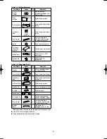
Table 1-3 (Ceiling-Mounted)
Part Name
Figure
Q’ty
Remarks
Special
washer
4
For temporarily
suspending indoor unit
from ceiling
Drain
insulator
T10
1
For drain hose joint
Flare insulator
T5
T3
2
sets
For gas and liquid tube
joints
Insulating
tape
White
(heat-
resisting)
2
For gas and liquid flare
joints
Vinyl clamp
8
For flare and drain
insulator (Field supply
for Spanish version)
Eyelet
1
For power supply inlet
Full-scale
installation
diagram
1
Printed on container box
Drain hose
L140
1
For main unit + PVC
pipe joints
Hose band
2
For drain hose
connection
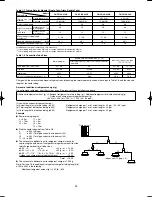
Table 1-4 (Concealed-Duct)
Part Name
Figure
Q’ty
Remarks
Washer
8
For suspending indoor
unit from ceiling
Flare insulator
2
For gas and liquid tubes
Insulating
tape
2
For gas and liquid tubes
flare nuts
Dain insulator
1
For drain hose joint
Hose band
1
For securing drain hose
Packing
1
For drain joint
Drain hose
1
Sealing putty
1
For sealing recessed
portion of power supply
Vinyl clamp
8
For flare and drain
insulators (Field supply
for Spanish version)
Booster
cable*
1
Connector for
changeover to HT tap
* Booster cable is housed inside the electrical component box.
●
Use M10 or 3/8" suspension bolts.
●
Suspension bolts and nuts are field supply.
Airwell̲PAC-i̲eng.indb 8
Airwell̲PAC-i̲eng.indb 8
2009/07/09 16:13:14
2009/07/09 16:13:14
Содержание OU-PSINV-25HR
Страница 75: ...75 ...