


56
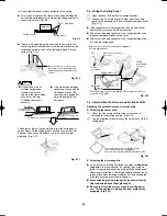
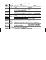
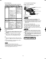
10-16-3. Setting the outdoor unit system addresses
For basic wiring diagram 2 (Set the system addresses: 1, 2,...)
ON
1
2
0
Outdoor unit control PCB
DIP switch
System address
System address rotary switch
(Set to “0” at time of shipment)
System address rotary switch
10s
20s
ON
OFF
3 – 6 HP
Fig. 10-13
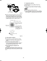
System address
No.
System address
10s digit
(2P DIP switch)
System address
1s place
(Rotary switch)
0 Automatic address
(Setting at shipment = “0”)
Both OFF
ON
1
2
ON
OFF
“0” setting
1 (If outdoor unit is No. 1)
Both OFF
ON
1
2
ON
OFF
“1” setting
2 (If outdoor unit is No. 2)
Both OFF
ON
1
2
ON
OFF
“2” setting
11 (If outdoor unit is No. 11)
10s digit ON
ON
1
2
ON
OFF
“1” setting
21 (If outdoor unit is No. 21)
20s digit ON
ON
1
2
ON
OFF
“1” setting
30 (If outdoor unit is No. 30)
10s digit and 20s
digit ON
ON
OFF
ON
1
2
“0” setting
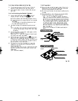
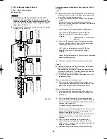
3 – 6 HP
System address rotary switch
System address 10s digit and 20s digit
DIP switch
Automatic address
button (black)
Terminal plug (black)
3 – 6 HP
System address rotary switch
System address 10s digit and 20s digit
DIP switch
Automatic address
button (black)
Terminal plug (black)
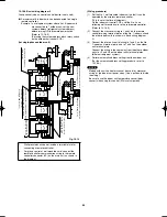
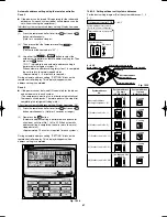
10-16-4. Automatic address setting from the outdoor unit
When there are multiple outdoor units as shown in basic wiring
diagram 2
●
If the power can be turned ON separately for the indoor and
outdoor units in each system (indoor unit addresses can be
set without operating the compressor):
(1) Turn ON the indoor and outdoor unit power for refrigerant
system 1.
Press and hold the automatic address setting button
(black) for 1 second or longer at the outdoor unit where the
power was turned ON.
↓
Communication for automatic address setting begins. LED
1 and 2 on the outdoor unit control PCB blink alternately,
and turn OFF when address setting is completed.
↓
<Approximately 4 – 5
minutes are required.>
(2) Next, turn ON the power only at the indoor and outdoor
units in a different system. Press the automatic address
setting button (black) on the outdoor unit.
↓
LED 1 and 2 on the outdoor unit control PCB blink
alternately, and turn OFF when address setting is
completed. Repeat the same procedure for each system
and complete automatic address setting.
↓
(3) Operation using the remote controller is now possible.
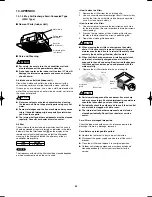
10-16-5. Indoor unit remote controller main-sub setting
●
When multiple wall-mounted indoor units are installed for
group control in a simultaneous-operation multi system, set
the control PCB at the No. 2 and following wall-mounted
units to “Sub remote control”.
If a wired remote controller is used, set the wired remote
controller to “Sub”.
If 2 wireless remote controllers are used, set the wireless
PCB (DIP switch) on the second remote controller to “Sub”.
Airwell̲PAC-i̲eng.indb 56
Airwell̲PAC-i̲eng.indb 56
2009/07/09 16:13:39
2009/07/09 16:13:39
Содержание OU-PSINV-25HR
Страница 75: ...75 ...