53
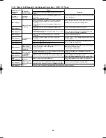
10-15. Table of Self-Diagnostic Functions and Corrections
Wired remote
controller
display
(Field supply)
Indoor unit
receiver lamp
Cause
Correction
1:1 connection (Single type)
Group connection
(Simultaneous multi
system)
Nothing is
displayed
Nothing is
displayed
• Indoor operation switch is OFF.
• Indoor unit power is not ON.
• Same at left.
• Set the indoor operation switch ON.
• Turn ON the indoor unit power.
E01
displayed
Operating lamp
is blinking.
• Automatic address setting has not been
completed.
• Inter-unit control wiring is cut or is not
connected correctly.
• Same at left.
• Check the inter-unit control wiring.
• Perform automatic address setting
(See 10-16).
E14
displayed
——————
• Remote controller
communication
wiring is cut or is not
connected correctly.
• Check the remote controller communication
wiring.
• Perform automatic address setting again.
E04
displayed
Standby lamp is
blinking.
• Indoor-outdoor inter-unit wiring is not
connected correctly.
• Same at left.
• Connect the wiring correctly.
E06
displayed
——————
• Inter-unit control
wiring is cut or is not
connected correctly.
• Refer to 10-16 System Control, and make
the correct settings.
E15
displayed
• Indoor unit capacity is too low.
• Same at left.
• Check that the total capacities of the indoor
and outdoor units are appropriate.
E16
displayed
• Indoor unit capacity is too high.
• Same at left.
• Reverse 2 phases of the outdoor unit
3-phase power and connect them correctly.
P05
displayed
Operation lamp
and Standby
lamp are blinking
alternately.
• Reversed phase in the outdoor unit
single-phase or open phase in the
outdoor unit 3-phase power.
• Same at left.
• Connect the units correctly.
L02
displayed
Both the
Operation lamp
and Standby
lamp are blinking
together.
• Indoor-outdoor unit type mismatch.
• Same at left.
• Connect the units correctly.
L13
displayed
• Indoor-outdoor units are not setting
correctly.
• Same at left.
• Connect the units correctly.
L04
displayed
——————
• Outdoor unit address is
duplicated.
• Connect the units correctly.
L07
displayed
——————
• Remote controller
communication wiring
is connected to the
indoor unit, however,
it is set for individual
operation.
• Perform automatic address setting
(See 10-16).
P15
displayed
Operation lamp
and Standby
lamp are blinking
alternately.
• No gas
• Same at left.
• Check the refrigerant cycle (for gas leaks).
Airwell̲PAC-i̲eng.indb 53
Airwell̲PAC-i̲eng.indb 53
2009/07/09 16:13:39
2009/07/09 16:13:39
Содержание OU-PSINV-25HR
Страница 75: ...75 ...


