


57
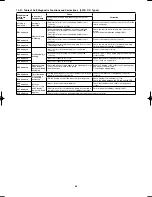
10-16-6. Indoor unit address setting
●
If multiple single-type units are installed in the same room,
the addresses can be set to prevent signal interference.
By coordinating the numbers of the indoor unit (wireless
PCB) and remote controller addresses, up to 6 indoor units
can be controlled independently by their respective remote
controllers.
Independent control is not possible when a simultaneous-
operation multi system is used.
●
Checking the addresses
Press the remote controller address button to display the
current address on the remote controller display.
If this address matches the indoor unit (wireless PCB)
address, the buzzer will sound.
(If ALL is set, the buzzer will always sound.)
If ALL is set, operation is possible regardless of the indoor
unit address.
Point the remote controller toward the receiver (indoor unit)
that you wish to operate, and send the operation signal.
●
Remote controller address setting
Press and hold the address button for 4 seconds or longer
to display the address on the remote controller display. The
current address starts blinking.
The address changes each time the remote controller
address button is pressed: ALL
→
1
→
2
→
3
→
...
→
6.
Set the address to match the remote controller you wish to
operate.
When the SET button is pressed, the address stops blinking
and displays for 5 seconds. The buzzer sounds if the
address matches the indoor unit.
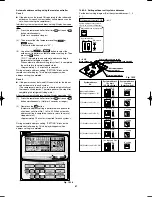
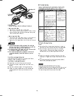
Remote
controller
address
display
Address
ALL
Address
1
Address
2
Address
3
Indoor unit
PCB address,
DIP switch
12
3
6 5 4
3 2 1
ON
ON
OFF
Address
12
3
6 5 4
3 2 1
ON
ON
OFF
Address
12
3
6 5 4
3 2 1
ON
ON
OFF
Address
12
3
6 5 4
3 2 1
ON
ON
OFF
Address
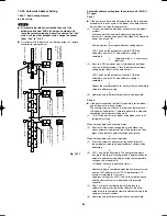
For address switches 1, 2, and 3, turn DIP switch 1 to OFF.
For address switches 4, 5, and 6, turn DIP switch 1 to ON.
1
2
3
ON
Address switch
Test
Remote controller
Sub On
Main Off
Indoor unit control PCB
2 HP
DIP switch
(SW101)
Address switch
(SW102)
Indoor unit control PCB
3 HP
DIP switch
(SW101)
Address switch
(SW102)
Fig. 10-14
■
4WK, C, D Types (for Link Wiring)
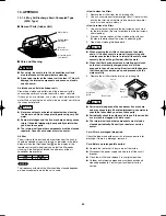
10-17. Caution
This unit may be used in a single-type refrigerant system
where 1 outdoor unit is connected to 1 indoor unit, and also
in a system where 1 outdoor unit is connected to multiple
indoor units (maximum 4 < Double-Twin >).
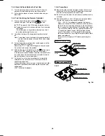
●
This test run explanation describes primarily the procedure
when using the wired remote controller.
●
If link wiring is used, set the outdoor unit system address
to allow the combination of indoor and outdoor units to be
identified. At the same time, indicate the indoor-outdoor unit
combination number in a location where it can be checked
easily (near the indoor unit nameplates). (This number will
be required for subsequent maintenance. Refer to 10-22-2,
-3, -4.)
●
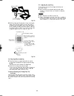
Request that the customer be present when the test run is
performed. At this time, explain the operation manual and
have the customer perform the actual steps.
●
Be sure to pass the manuals and warranty certificate to the
customer.
●
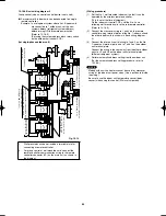
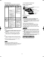
Check that the 220 – 240 V AC wiring is not connected to the
inter-unit control wiring connector terminal.
If 220 – 240 V AC is accidentally applied, the indoor or
outdoor unit control PCB fuse (0.5 A for both indoor and
outdoor units) will blow in order to protect the PCB. Correct
the wiring connections, then disconnect the 2P connectors
(indoor: blue, OC) (outdoor: blue, serial 1) that are
connected to the PCB, and replace them with 2P connectors
(indoor: brown, EMG) (outdoor: brown, serial 2).
If operation is still not possible after changing the brown
connectors, try cutting the varistor (black) (both indoor and
outdoor).
(Be sure to turn the power OFF before performing this work.)
CHK (2P plug)
2P connector (brown)
2P connector (blue)
Varistor (black)
VA100
Fuse 0.5A
Indoor unit control PCB
Fig. 10-15
Outdoor unit control PCB
Varistor (black)
VA002
Serial 2 (brown) connector
Serial 1 (blue) connector
Fuse
0.5 A
3 – 5 HP
Outdoor unit control PCB
Varistor (black)
VA002
Serial 2 (brown) connector
Serial 1 (blue) connector
Fuse
0.5 A
3 – 5 HP
Airwell̲PAC-i̲eng.indb 57
Airwell̲PAC-i̲eng.indb 57
2009/07/09 16:13:40
2009/07/09 16:13:40
Содержание OU-PSINV-25HR
Страница 75: ...75 ...