55
10-16-2. Basic wiring diagram 2
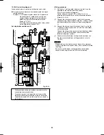
Group control (when a central control device is not used)
●
A maximum of 8 indoor units can be connected to a single
remote controller.
Example: In a refrigerant system where 2 or 3 indoor units
are connected to 1 outdoor unit, set the new
system address (refrigerant system address)
before turning ON the remote power switch.
(Refer to 10-16-3.)
(Set using the system address black rotary switch
on the outdoor unit control PCB.)
(for single-phase outdoor unit)
1
2
1
2
1
2
U2 U1
L
N
U2 U1
L
N
1
2
U2 U1
L
N
N
L
1
2
N
L
1
2
U2 U1
L
N
1
2
U2 U1
L
N
Leakage breaker
System address rotary switch
(Change the setting to “1”.)
Wall-
mounted
type
Indoor
unit
No. 1
Indoor
unit
No. 2
Ground
Indoor
unit
No. 3
Ground
Indoor
unit
No. 4
Ground
Indoor
unit
No. 5
Ground
System address rotary switch
(Change the setting to “2”.)
Leakage breaker
Leakage breaker
Outdoor unit
Outdoor unit
Ground
Ground
Indoor power crossover
wiring – up to 16 units
(no-heater units only)
Inter-unit control wiring
Connection to lead wires
(Black / White)
Remote controller communication wiring
for group control (field-supply wiring)
Up to 8 units can be
set for group control
(Thickness 0.5 – 2.0 mm
2
,
total length 200 m or less)
Leakage breaker
Ground
Fig. 10-12
1.
Wall-mounted units do not include a terminal plate for
connecting a remote controller.
2.
For group control of wall-mounted units, connect the
remote controller communication wiring to the remote
controller connector (2P) on the main unit, as shown in
the diagram.
(Wiring procedure)
(1) Set the No. 1 wall-mounted indoor unit so that it can be
operated by the wireless remote controller.
(This is set at the time of shipment.)
On the indoor unit control PCBs, set the No. 2 and
following wall-mounted units to the sub remote controller.
(Refer to 10-16-5.)
(2) Connect the crossover wiring to 1 and 2 on the remote
controller wiring terminal plates of the No. 1 indoor unit and
the other indoor units (as shown in Basic wiring diagram
2).
(3) Connect the inter-unit control wiring to 1 and 2 on the No.
1 indoor unit terminal plate, and to 1 and 2 on the outdoor
unit terminal plate.
Connect the wiring in the same way from the other outdoor
units to U1 and U2 on the indoor units terminal plates
(different refrigerant system).
(4) Perform automatic address setting from the outdoor unit.
(For the automatic address setting procedure, refer to
10-16-4.)
NOTE
* Models with auxiliary heaters cannot be used for “crossover
wiring” of the indoor unit power wires. (Use a pull box to divide
the wiring.)
* Be sure to use the indoor unit temperature sensor (body
sensor) when using this control. (Status at shipment)
Airwell̲PAC-i̲eng.indb 55
Airwell̲PAC-i̲eng.indb 55
2009/07/09 16:13:39
2009/07/09 16:13:39
Содержание OU-PSINV-25HR
Страница 75: ...75 ...

