


29
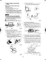
3-21. Checking the Drainage
After wiring and drain piping are completed, use the following
procedure to check that the water will drain smoothly. For this,
prepare a bucket and wiping cloth to catch and wipe up spilled
water.
(1) Connect power to the power terminal board (R, S
terminals) inside the electrical component box.
(2) Remove the tube cover and slowly pour about 1,200 cc
of water through the opening into the drain pan to check
drainage.
(3) Short-circuit the check pin (CHK) on the indoor control
circuit board and operate the drain pump. Check the water
flow through the transparent drain port and see if there is
any leakage.
CAUTION
Be careful since the fan will start when you short the pin on
the indoor control board.
(4) When the drainage check is complete, open the check pin
(CHK) and remount the insulator and drain cap onto the
drain inspection port.
Water intake
Fig. 3-66
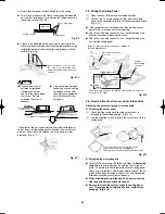
3-22. Increasing the Fan Speed
If external static pressure is too great (due to long extension
of ducts, for example), the airflow volume may drop too low at
each air outlet. This problem may be solved by increasing the
fan speed using the following procedure:
(1) Remove 4 screws on the electrical component box and
remove the cover plate.
(2) Disconnect the fan motor sockets in the box.
(3) Take out the booster cable (sockets at both ends) clamped
in the box.
(4) Securely connect the booster cable sockets between the
disconnected fan motor sockets in step 2 (Fig. 3-67).
Electrical component box
Fan
motor
Booster cable
(At shipment)
(Booster cable installed)
Fan motor socket
Booster cable
Fig. 3-67
(5) Place the cable neatly in the box and reinstall the cover
plate.
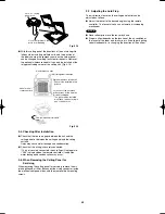
Indoor Fan Performance
5
0
50
100
0
5
10
15
150
10
HT
H
M
L
15
0
50
0
5
10
15
150
10
HT
M
L
100
H
12 Type
16, 18 Type
AirFlow (m
3
/minute)
External Static Pressure
External Static Pressure
(Pa)
(Pa)
Limit line
Limit line
Limit line
Limit line
(mmAq)
(mmAq)
AirFlow (m
3
/minute)
20
0
50
0
5
10
15
150
10
HT
H
L
100
M
30
0
50
0
5
10
15
150
20
HT
L
100
M
H
AirFlow (m
3
/minute)
25 Type
36 Type
External Static Pressure
External Static Pressure
(Pa)
(Pa)
Limit line
Limit line
Limit line
Limit line
(mmAq)
(mmAq)
AirFlow (m
3
/minute)
30
40
18
22
26
30
34
38
42
0
50
0
5
10
15
150
20
L
100
M
H
M
H
L
0
50
150
100
HT
HT
N OT E
0
5
10
15
AirFlow (m
3
/minute)
48 Type
60 Type
External Static Pressure
External Static Pressure
(Pa)
(Pa)
Limit line
Limit line
Limit line
Limit line
(mmAq)
AirFlow (m
3
/minute)
HT : Using the booster cable
H : At
shipment
Fig. 3-68
■
How to read the diagram
The vertical axis is the external static pressure (Pa) while
the horizontal axis represents the airflow (m
3
/minute). The
characteristic curves for “HT”, “H”, “M” and “L” fan speed control
are shown. The nameplate values are shown based on the
“H” airflow. For the 25 type, the airflow is 18 m
3
/minute, while
the external static pressure is 49 Pa at “H” position. If external
static pressure is too great (due to long extension of ducts,
for example), the airflow volume may drop too low at each air
outlet. This problem may be solved by increasing the fan speed
as explained above.
(mmAq)
Airwell̲PAC-i̲eng.indb 29
Airwell̲PAC-i̲eng.indb 29
2009/07/09 16:13:26
2009/07/09 16:13:26
Содержание OU-PSINV-25HR
Страница 75: ...75 ...