48
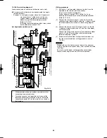
(Wiring procedure)
(1) Connect the remote controller to the indoor unit remote
controller wiring terminal plate (1, 2). (Remote controller
wiring)
(2) Connect the indoor units (U1, U2) and the outdoor units (1,
2). Connect the other outdoor units and indoor units (with
different refrigerant systems) in the same way. (Inter-unit
control wiring)
Connect the remote controller communication wiring to the
indoor units (U1, U2) for each refrigerant system. (Inter-
unit control wiring)
(3) Connect the remote controller communication wiring (2
wires) from the remote controller wiring terminal plate (1,
2) on the indoor unit (unit where the remote controller
is connected) to the remote controller terminal plates
(1, 2) on the other indoor units. (Remote controller
communication wiring)
(4) Turn ON both the indoor and outdoor unit power and
perform automatic address setting from the remote
controller. (For the automatic address setting procedure,
refer to 10-8-4.)
NOTE
* Models with auxiliary heaters cannot be used for crossover
wiring of the indoor unit power wires. (Use a pull box to divide
the wiring.)
Be sure to use the indoor unit temperature sensor (body
sensor) when using this control. (Status at shipment.)
Airwell̲PAC-i̲eng.indb 48
Airwell̲PAC-i̲eng.indb 48
2009/07/09 16:13:36
2009/07/09 16:13:36
Содержание OU-PSINV-25HR
Страница 75: ...75 ...


