259
3
English URL
www.agilent.com/find/products
English URL
www.agilent.com/find/products
Overview
Overview
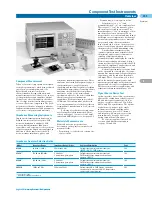
Component Test Instruments
Component Measurement
Today’s electronic components are designed
for higher performance, while being reduced
in size, power consumption, and cost.
Efficient and accurate component
characterization, design evaluation, and
manufacturing test are critical to the success
of component users and suppliers. Agilent
Technologies offers the industry’s broadest
line of component test instruments for pas-
sive as well as active components. The prod-
ucts in this section are designed to measure
fundamental impedance-related parameters
of electronic components and materials.
Impedance Measuring Instruments
Impedance measuring instruments can be
divided into two general categories: LCR
meters and impedance analyzers. LCR
meters primarily measure inductance,
capacitance, and resistance of the test device
at spot frequencies. Impedance analyzers, in
addition to all the functions of the LCR
meter, measure impedance, phase, and
sometimes transmission parameters. These
analyzers have extended frequency range, a
synthesized source, swept frequency
capability, and excellent frequency resolution.
Combination network/spectrum/impedance
analyzers offer the benefits of impedance
analysis as well as vector-network and
spectrum analysis. See the Selection Guides
that follow for general instrument
capabilities. For higher frequencies (above
3 GHz) in a 50
Ω
environment, a dedicated
vector-network analyzer is the best solution
for impedance measurements. See Network
Analyzers.
Selecting a test fixture is as important
as selecting the right instrument. Agilent
offers a wide range of accessories for axial,
radial, and SMD chip devices. See page 261.
Materials Measurements
Materials have two properties that
determine how they interact with electro-
magnetic fields:
• Permittivity (
) or dielectric constant for
electric fields
• Permeability (µ) for magnetic fields
Permittivity (
*=
’
-j
”
) and
permeability (
µ
*=
µ
’
- j
µ
”
) are complex values.
The real part (
’
or
µ
’
) is a measure of how
much energy is stored in a material. The
imaginary part (
”
or
µ
”
) is a measure of how
much energy is lost in a material. These
properties are not constant and may change
with frequency or temperature, for example.
Accurate measurements of these material
properties during characterization or
inspection help to achieve the best perfor-
mance for a given application while short-
ening design cycles and minimizing scrap.
A materials measurement system
consists of an instrument, a fixture to hold
the material, and software or firmware to
calculate complex permittivity or
permeability values and display the results.
For material testing applications, Agilent
currently offers three types of solutions: LCR
meter-based, impedance analyzer-based, and
network analyzer-based systems.
Agilent offers fixture accessories based
on the open-ended coaxial probe, the trans-
mission line measurement, the parallel plate
capacitance, and the inductor impedance
technique. These choices allow you to best
match the fixture, frequency range, and
measurement technique with your material’s
physical and electrical test requirements.
The chart of material test applications and
solutions is shown in the next page 260.
Signal Source Device Test
Agilent provides an excellent performance
analyzer for evaluating nearly all types of
RF and microwave signal source device
such as crystal oscillators, VCOs, DROs,
RFICs, and PLL synthesizers. The Agilent
Signal Source Analyzer is the single
instrument solution enabling phase
noise, frequency, power, DC current,
and frequency/phase/power over time
measurements. See page 268 for the
Agilent Signal Source Analyzer.
For specific applications such as
resonator and filter measurements,
see page 163 and 164.
Impedance Analyzer Selection Guide
Model
Frequency Range
Impedance Range/Other
Additional Information
Page
4294A
40 Hz to 110 MHz
25 m
Ω
to 40 M
Ω
*
Color display, equivalent circuit analysis,
266
IBASIC, LAN I/F, SMD fixtures
4395A**
100 kHz to 500 MHz
2
Ω
to 5 k
Ω
*
Color display, equivalent circuit analysis,
164
S-parameters, gain-phase
SMD fixture vector-network and spectrum
analysis , IBASIC
4396B**
100 kHz to 1.8 GHz
2
Ω
to 5 k
Ω
*
Color display, equivalent circuit analysis,
166
S-parameters, gain-phase
SMD fixture vector-network and spectrum
analysis , IBASIC
E4991A
1 MHz to 3 GHz
200 m
Ω
to 20 k
Ω
Color display, VBA, SMD fixtures, equivalent
262
circuit analysis, material, LAN I/F, temperature
characteristic measurement
* 10% accuracy range
** with 4395A/4396B-010 and 43961A
Содержание All
Страница 1: ......

