


211
3
English URL
www.agilent.com/find/products
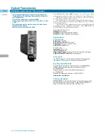
N5980A
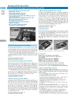
3.125 Gb/s Manufacturing Serial BERT N5980A for Electrical and Optical Devices
Serial Bit Error Ratio Tester
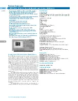
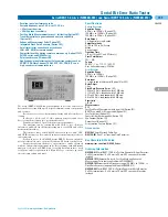
The Agilent N5980A 3.125 Gb/s Serial BERT is ideal for manual or
automated manufacturing test of electrical and optical devices
running at speeds between 125 Mb/s and 3.125 Gb/s. It addresses all
common standard speeds via selectable bit rates.
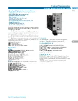
Easy-to-use and Cost Efficient
The software user interface has one standard or one advanced
screen to ensure intuitive use for operators. It makes the instrument
easy to use and easy to learn.
Twice the Measurement Throughput
By using both the electrical and optical (SFP) interfaces concurrently,
you can double your measurement throughput (electrical in/optical
out and vice versa).
Automation Made Easy
The remote programmability of the user interface, using SCPI –
syntax, makes it simple to integrate the N5980A into other
programs.
PRBS, K28.5 Pattern or Clock Generation and Integrated
Clock Data Recovery
The N5980A can generate standard PRBS polynomials, K28.5
(‘Comma’) characters and different sub-rate clocks (/2 to /20). It can
also inject errors with an adjustable error ratio. The receiver has a
clock-data – recovery (CDR) built-in and differential inputs (SMA)
for signals from 50 mVpp to 2 Vpp amplitude.
Standard (SFP) Optical Module Plug-in
The instrument has a standard SFP- female connector. This enables
all different kind of user-selectable optical modules (e.g for multi-
mode/single-mode fiber at 850 nm, 1310 nm and 1550 nm for the test
set-up).
Small Size
Its very small size allows the N5980A to fit on any bench and in any
automated setup. The dimensions are, 228 mm (W) x 59 mm (H) x
246 mm (D) (Bench top dimensions).
Specifications
Data Rates
Fast Ethernet: 125 Mb/s
OC-3: 155.52 Mb/s
OC-12: 622.08 Mb/s
OC-48: 2.48832 Gb/s
OC-48 with FEC: 2.66606 Gb/s
1 x FC: 1.0625 Gb/s
2 x FC: 2.125 Gb/s
1 x Gigabit Ethernet: 1.25 Gb/s
XAUI: 3.125 Gb/s
Accuracy: ± 50 ppm
Operating System
The software supplied runs on Windows 2000 or XP with .NET v2.0,
by a USB 2.0 interface
Pattern Generator
Pattern
PRBS: 2
7
–1, 2
15
–1, 2
23
–1, 2
31
–1
Data pattern: K28.5
Clock pattern: data rate divide by n, n = 2, 4, 8, 10, 16, 20
The pattern can be individually adjusted for pattern generator electrical
out and optical out
Error Injection
Fixed electrical and optical error inject:
Fixed error ratios of 1 error in 10
n
bits, n = 3, 4, 5, 6, 7, 8, 9
Single error injection
Separate error ratios can be adjusted for pattern generator electrical out
and optical out
Pattern Generator Electrical Out
A differential electrical output is provided on the front-panel
Output Amplitude
ECL
850 mVpp typ., single-ended
1700 mVpp typ., differential
LVDS
400 mVpp typ., single-ended
800 mVpp typ., differential
Jitter
0.05 UI typ. @ OC-12
0.08 UI typ. @ GbE
0.15 UI typ. @ OC-48
Pattern Generator Optical Out
A standard SFP housing is provided
Minimum number of insertion/deinsertion cycles: 200
Error Detector
A differential electrical input is provided on the front-panel
Data rate is the same as pattern generator
Pattern
The following patterns are supported:
PRBS: 2
7
–1, 2
15
–1, 2
23
–1, 2
31
–1
Data Input
differential AC coupled
Max. Input Amplitude
1 Vpp, single-ended
2 Vpp, differential
Clock Data Recovery
Internal CDR
Impedance
100 Ohms nominal
Sensitivity
<50 mV
Synchronization
Automatically on level, polarity, phase, bit and pattern
Operating System
The software supplied runs on Windows 2000 or XP with .NET v2.0,
by a USB 2.0 interface
Key Literature & Web Link
www.agilent.com/find/manufacturing_bert
Ordering Information
N5980A
3.125 Gb/s Serial BERT
• Standard measurements at rates between 125 Mb/s and
3.125 Gb/s
• Generation of Pseudo Random Bit Sequence (PRBS) polynomials
and a K28.5 pattern at Low Voltage Differential Signal (LVDS) or
Emitter Coupled Logic (ECL) levels
• Flexible connections to the device under test via 3.5 mm differen-
tial electrical coax connectors and/or standard optical SFP
module plug-ins
• Optical and electrical error injection (once or at selectable
Bit-Error-Ratio)
• Analysis of gated Bit-Error-Ratio with display of the absolute
number of errors and selectability of gate time
• Dramatically simplified transceiver measurements that provide
just the essential tests via the one page graphical user interface
(running on an external Windows
®
XP PC via a USB 2.0 interface)
• Full programmability of all graphical user interface features from
another software program, making automation in manufacturing
an easy task
Содержание All
Страница 1: ......


