


246
3
English URL
www.agilent.com/find/products
53131A
53132A
53181A
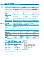
Frequency and Time Interval Counters (cont.)
Electronic Counters
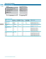
Optional High-Frequency Channels
Frequency
Coupling
Power Range
Damage
Range
and Sensitivity
Level
53181A-015
1
100 MHz to
ac
–27 dBm to +19 dBm
5 V
rms
1.5 GHz
1.5 GHz
channel
531xxA-030
100 MHz to
ac
–27 dBm to +19 dBm
5 V
rms
3.0 GHz
3.0 GHz
(100 MHz to 2.7 GHz)
channel
–21 dBm to +13 dBm
(2.7 GHz to 3 GHz)
531xxA-050
200 MHz to
ac
–23 dBm to +13 dBm
25 dBm
5.0 GHz
5.0 GHz
channel
531xxA-124
200 MHz to
ac
–23 dBm to +13 dBm
25 dBm
12.4 GHz
12.4 GHz
channel
1
Option 015 is available only for 53181A counters.
Ordering Information
53131A
Frequency Counter
53132A
Frequency Counter
53181A
RF Counter
531xxA-001
Medium-Stability Timebase
531xxA-010
High-Stability Timebase
53132A-012
High-Stability Timebase (53132A only)
53181A-015
1.5 GHz Ch. w/BNC Connector (53181A only)
531xxA-030
3 GHz Channel with BNC Connector
531xxA-050
5 GHz Channel with Type-N Connector
531xxA-124
12.4 GHz Channel with Type-N Connector
531xxA-060
Rear-Panel Connectors
531xxA-A6J
ANSI Z540 Compliant Calibration
531xxA-1CM
Rackmount Kit
34161A
Accessory Pouch
34131A
Hard Transit Case
Abridged Measurement Specification & Characteristics
53131A
53132A
53181A
Measurements
Frequency, frequency ratio, time interval, period, rise/fall time, positive/negative
Frequency, frequency ratio
pulse width, duty cycle,phase (CH 1 to CH 2), totalize, peak voltage, time interval
(with optional CH 2),
average, time interval delay
period, peak voltage
Analysis
Automatic limit testing, math (scale and offset), statistics (minimum, maximum, mean, standard deviation).
Statistics available on all measurements or only measurements that fall within limits.
Measurement Characteristic
Frequency range
CH 1 & 2: dc – 225 MHz
CH 1 & 2: dc – 225 MHz
CH 1: dc – 225 MHz
Frequency resolution
10 digits/s
12 digits/s
10 digits/s
Time interval
500 ps
150 ps
—
resolution (LSD)
Measurement speed
Up to 200 meas/s over GPIB
Up to 200 meas/s over GPIB
Up to 200 meas/s over GPIB
Voltage Range & Sensitivity
(Sinusoid)
DC to 100 MHz
20 mV
rms
to ±5 Vac + dc
20 mV
rms
to ±5 Vac + dc
20 mV
rms
to ±5 Vac + dc
100 MHz to 200 MHz
30 mV
rms
to ±5 Vac + dc
30 mV
rms
to ±5 Vac + dc
30 mV
rms
to ±5 Vac + dc
200 to 225 MHz
40 mV
rms
to ±5 Vac + dc
40 mV
rms
to ±5 Vac + dc
40 mV
rms
to ±5 Vac + dc
Input Conditioning
(Independently selectable on CH 1 & 2)
(Independently selectable on CH 1 & 2)
(Selectable on CH 1)
Impedance, coupling
1 M
Ω
or 50
Ω
, ac or dc
1 M
Ω
or 50
Ω
, ac or dc
1 M
Ω
or 50
Ω
, ac or dc
Low pass filter
100 kHz, switchable
100 kHz, switchable
100 kHz, switchable
Attenuation
x1 or x10
x1 or x10
x1 or x10
External Timebase Reference Input
1, 5, 10 MHz
10 MHz
1, 5, 10 MHz
Trigger
CH 1 & 2
CH 1 & 2
CH 1
Trigger on rising/falling edge; set level by percent of signal level or absolute voltage; set sensitivity to LOW, MED, or HIGH
Gating and Arming
Auto, manual (set gate time or number of digits of resolution); external, delay (expanded on 53132A)
Interfaces
GPIB (IEEE 488.1 and 488.2) with SCPI-compatible language; talk only RS-232
Software
Includes IntuiLink Connectivity Software
Power
100 to 120 VAC ± 10% –50, 60 or 400 Hz ± 10%
220 to 240 VAC ± 10% –50 or 60 Hz ± 10%
AC line voltage selection is automatic
Net Weight/Size
3 kg (6.5 lbs), 88.5 mm H x 212.6 mm W x 348.3 mm D (3.54 in x 8.50 in x 13.932 in)
For full specifications, request a Product Overview, or visit our web site:
www.agilent.com/find/counter
Standard and Optional High-Stability Timebases
Standard
Medium Stability
High Stability Oven
Ultra High Stability Oven
(0° to 50°C)
Oven (Option 001)
(Option 010)
(Option 012, 53132A only)
Temperature Stability
<5 x 10
–6
<2 x 10
–7
<2.5 x 10
–9
<2.5 x 10
–9
(referenced to 25°C
)
Aging Rate
Per Day
<4 x 10
–8
<5 x 10
–10
<1 x 10
–10
(after 30 days)
Per Month
<3 x 10
–7
<2 x 10
–7
<1.5 x 10
–8
<3 x 10
–9
Per Year
<2 x 10
–8
Turn-on Stability vs. Time
<2 x 10
–7
<5 x 10
–9
<5 x 10
–9
(in 30 minutes)
(referenced to 2 hours)
(referenced to 24 hours)
(referenced to 24 hours)
Calibration
Manual Adjust
Electronic
Electronic
Electronic
Note that power to the time base is maintained when the counter is placed in standby via the front panel switch. The internal fan will continue to operate under this condition to maintain
long-term instrument reliability.
}
Содержание All
Страница 1: ......


