background image


AEQ


CAPITOL


Ultra-compact digital audio mixer 


78

  “

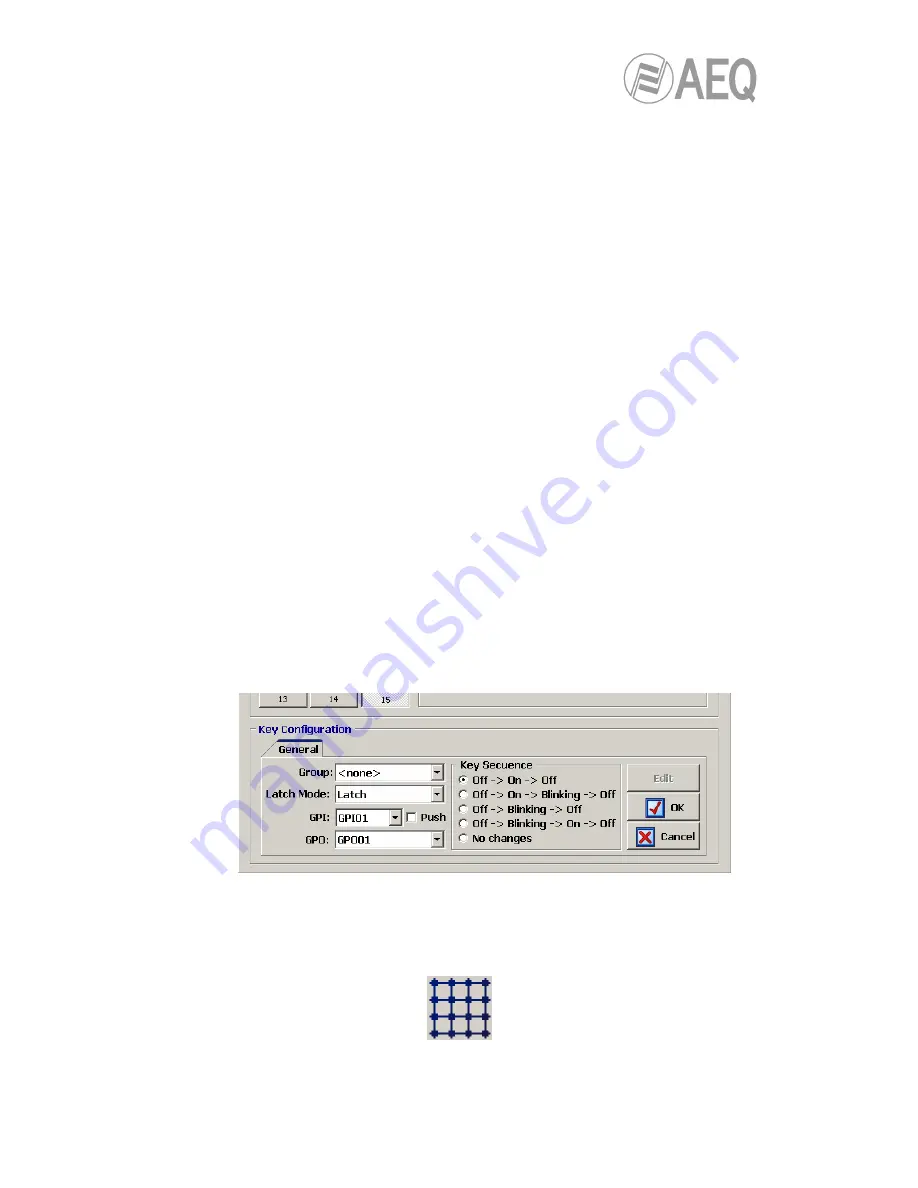
Latch Mode

allows you to configure the key as “Latch” or “Non Latch”, so after you 

press it, the key stays fixed or not. When a key is configured as “Non Latch”, it executes 
the associated function only while it remains pressed. 

  “

GPI

:

 allos you to select the physical GPI input, in the section of system common I/O's, 

associated to the programmable key activation. 

  “

Push

:

 when you associates a GPI and a GPO to the same key and you active this 

checkbox, the GPO is automatically activated when GPI is received. When “Push” 
checkbox is not active, this automatic activation is not made. 

  “

GPO

:

 allows you to select the physical GPO output, in the section of system common 

I/O's, associated to the programmable key activation. 

  “

Key Secuence

:

 allows you to select the operating sequence of the programmable 

key: 

o

  “

Off-On-Off

initially the key is off, it turns on when the programmable key is 

pressed (or when the associated GPI is activated) and off when it’s pressed 
again (or when the GPI is deactivated). From this point the cycle is re-initiated. 

o

  “

Off-On-Blinking-Off

:

 initially the key is off, it turns on when the 

programmable key is pressed, starts blinking when the key is pressed again 
and turn off when it’s pressed again. From this point the cycle is re-initiated. 
When activation is through an associated GPI, the key turns on when the GPI is 
activated and starts blinking when it’s deactivated. 

o

  “

Off-Blinking-Off

initially the key is off, it starts blinking when the 

programmable key is pressed (or when the associated GPI is activated) and off 
when it’s pressed again (or when the GPI is deactivated). From this point the 
cycle is re-initiated. 

o

  “

Off-Blinking-On-Off

:

 initially the key is off, it starts blinking when the 

programmable key is pressed, turns on when the key is pressed again and turn 
off when it’s pressed again. From this point the cycle is re-initiated. When 
activation is through an associated GPI, the key starts blinking when the GPI is 
activated and turns off when it’s deactivated. 

o

  “

No changes

:

 this option is exclusively associated to GPIs. The key turns on 

when GPI is activated and keeps on until that GPI is deactivated, even if the 
key is pressed. 

  “

OK

allows you to accept the created or edited configuration. 

  “

Cancel

:

 allows you to reject the created or edited configuration. No change you may 

have made is saved. 


4.3.2.3. Configuration of 

Salvo

 programmable keys.


Programmable keys that are set to “Salvo” are used to activate/deactive a Salvo or group of 
conecctions and/or disconnections of several cross-point. A key set to this function is assigned 
with a dedicated icon. 


The lower part of the “Programmable Keys” submenu will allow you to configure the Salvo 
content.  

Содержание CAPITOL

Страница 1: ...AEQ CAPITOL ULTRA COMPACT DIGITAL AUDIO MIXER FOR BROADCAST APPLICATIONS USER S MANUAL ED 10 12 V 1 7 15 09 2014 Software version 3 29 July 2014 ...

Страница 2: ...ing section 14 2 1 2 5 Studio room monitoring section 15 2 1 2 6 Talkback 17 2 1 3 Wrist rest and side trims 18 2 2 Audio engine description 19 2 2 1 Power supply 20 2 2 2 Auxiliary connections 20 2 2 2 1 GPIO 20 2 2 2 1 1 Opto coupled GPI 21 2 2 2 1 2 Opto coupled GPO 21 2 2 2 1 3 Physical contact GPO 22 2 2 2 2 Ethernet Port 23 2 2 2 3 Control and studio monitors 24 2 2 2 4 CUE 24 2 2 2 5 Studio...

Страница 3: ...menu 73 4 3 Programmable Configuration menu 74 4 3 1 Routing Configuration submenu 74 4 3 2 Programmable Keys submenu 76 4 3 2 1 Basic configuration of programmable keys 76 4 3 2 2 Configuration of General programmable keys 77 4 3 2 3 Configuration of Salvo programmable keys 78 4 3 2 4 Configuration of Codec programmable keys 80 4 3 2 5 Configuration of Multiplex programmable keys 83 4 3 2 6 Confi...

Страница 4: ...ontrol power and simplicity of use has been combined into AEQ CAPITOL to meet from the most basic to advanced operation needs from an 8 faders control surface WARNING The cable that connects control surface and audio engine carries power supply In order to avoid any damage to the unit is VERY IMPORTANT to turn off the unit before connecting or disconnecting this cable All basic functions of activa...

Страница 5: ...uses Control communication via 10 100 Ethernet connection using TCP IP protocol Boot up using last used settings System signals can be assigned to any control channel System settings are stored in the on board memory up to 7 available memory positions 1 2 3 General features All system signals configurable for monitoring in Control Studio CUE Headphones and VU meters 2 direct routing buttons on eac...

Страница 6: ...control surface Gain control for microphone inputs from 36 to 19dB Selectable balance panoramic control on all channels Selective phase reverse Audio processing for 16 stereo signals up to 8 on fader plus 8 signals not visible on control surface Pre defined audio processing that allows manual adjustment Available audio effects 3 bands equalizer with adjustable Q value high pass and low pass filter...

Страница 7: ...gram are accomplished from this area The control surface incorporates all the keys displays faders encoders and VU meters required to operate the equipment There are two different areas on the AEQ CAPITOL control surface the area on the left that corresponds to the AUDIO CHANNELS controlled through faders 8 x 100mm faders and the CONTROL AND MONITORING AREA which is located to the right AEQ CAPITO...

Страница 8: ...on control gain dynamics EQ and balance Beneath this section an OLED display shows channel name and status for balance or pan Immediately under the display is located the Pre listen button CUE as well as the PROCESS LED that alerts with regards to the activation or changes of equalization dynamics compressors and limiters balance or gain By pressing the SELECT button the advanced configuration fun...

Страница 9: ...ION SOFTWARE of this manual 2 1 1 2 SELECT The control surface of AEQ CAPITOL offers the usual controls and indicators for a mixing console on each channel but AEQ CAPITOL also offers a wide range of possibilities for routing and processing beyond the physical options included in each channel These possibilities have been distributed in a logical manner within internal menus accessible from the ma...

Страница 10: ...n lit this indicates the activation or change of any of the following fields EQ filters dynamics compressors and limiters balance or gain These four processes EQ dynamics balance and gain are controlled from the internal menu associated with the SELECT button on the main screen of the Control and Monitoring section 2 1 1 6 Channel activation key The channel activation key also known as CHANNEL ON ...

Страница 11: ...les the overall management of the signals on the system including routing and control processes as well as monitoring of the signals used in developing the final program by means of the VU Meters and CUE control This control and monitoring section is divided into four main areas Control VU meters allows you to monitor visually the level of the audio signals from the master output and the CUE bus o...

Страница 12: ... bottom to top the first 25 LEDs are green followed by an area of 5 yellow LEDs to finish with an area of 10 red LEDs 0dB point or nominal value corresponds to the the first yellow LED adjacent to the last green LED Detail of control vumeters Both VU meters are set to function as IEC268 10 5ms 2dB vu meter only and the peak meter IEC268 17 300 ms vu meter Flying PPM superimposed VU meters CONTROL ...

Страница 13: ...the pressing of the key will trigger the execution of the programmed action but only remains active as long as you keep the button pressed All keys can be easily labelled removing the transparent plastic cover and inserting a text label AEQ supplies with the equipment a template that allows you to create these labels on clear acetate or plain paper 2 1 2 3 Main display The main screen is a two col...

Страница 14: ... encoders are represented and labelled on the display for easy operation 2 1 2 4 Control room monitoring section Located in the lower right corner of the AEQ CAPITOL control surface are a two coloured display three rotary encoders and four keys one of them SEL a short cut key In the two coloured OLED display are shown the output levels for the control monitoring signals and the selected sources in...

Страница 15: ...itor the audio signal Audition o SEL allows you to monitor any signal of the console previously selected by means of HP SOURCE encoder o CUE allows you to monitor the audio signal present on the CUE bus These four keys can have two working modes that are selected from the Configuration Software see section 4 2 4 of this manual o Mixer each key pressed adds the signal to be monitored to the summing...

Страница 16: ...ociated with the key SEL press to access a list of signals and turn the encoder to move up or down in the list of signals pushing the encoder a second time confirms the selection of the highlighted signal The four keys under the display allows to select the signal to monitor on studio speakers and headset from left to right o PROG allows you to monitor the audio signal Program o AUD allows you to ...

Страница 17: ...s immediately beneath the Studio and Control sections and the encoder LEVEL Talkback Level of the Studio monitoring section From left to right are MON talk back to studio monitors HP talk back to studio headphones The default configuration of the AEQ CAPITOL does not differentiate between primary and secondary headphones It is possible to establish a secondary group of headphone creating a salvo t...

Страница 18: ...ol surface This frame adopts the shape of a wrist rest at the lower side in oven dried lacquereed steel that suffers minimal wear of use AEQ CAPITOL TT The wooden side trims allow for an easy recognition of the equipment and are integer part of the chassis They also have the function as a finishing element for table top installations of the mixing console AEQ CAPITOL CS option on the other hand is...

Страница 19: ...xiliary signals configurations of the mixing console are fixed and defined from Factory 4 balanced microphone line level inputs 12 line level balanced mono analog inputs 4 AES S PDIF digital stereo inputs 8 line level balanced mono analog outputs 4 AES S PDIF digital stereo outputs 2 stereo input output USB computer connections Control and Studio headphone outputs Stereo unbalanced CUE output with...

Страница 20: ...rovided with the unit only IMPORTANT NOTE Do not connect this output to any device but the cotrol surface there is a severe risk of damage to other equipment or even the audio engine itself In order to avoid any damage to the unit is VERY IMPORTANT to turn off the unit before connecting or disconnecting this cable 2 2 2 Auxiliary connections This area of the AEQ CAPITOL back panel includes a wide ...

Страница 21: ...nformation please check chapter 2 2 6 of this manual GPI Inputs SUB D female 15 pins Pin Signal Pin Signal 1 GPI1 9 GND_GPI1 4 2 GPI2 10 GND_GPI1 4 3 GPI3 11 GND_GPI1 4 4 GPI4 12 Not connected 5 GPI5 13 GND_GPI5 8 6 GPI6 14 GND_GPI5 8 7 GPI7 15 GND_GPI5 8 8 GPI8 Please note that there is a common ground GND for inputs 1 to 4 and another one for inputs 5 to 8 Upon request this wiring kit can be sup...

Страница 22: ...D_GPO1 4 3 GPO3 11 GND_GPO1 4 4 GPO4 12 Not connected 5 GPO5 13 GND_GPO5 8 6 GPO6 14 GND_GPO5 8 7 GPO7 15 GND_GPO5 8 8 GPO8 Please note that there is a common ground GND for outputs 1 to 4 and another one for outputs 5 to 8 Upon request this wiring kit can be supplied with connectors explicitly specified by the customer For more information please refer to AEQ sales department or authorised distri...

Страница 23: ...AEQ can upon request provide fully finished cables and in special lengths For more information please refer to AEQ sales department or authorised distributors 2 2 2 2 Ethernet Port Located in the lower left part of AEQ CAPITOL back chassis you can find an Ethernet RJ45 10 100BaseT socket labelled LAN for connection to external devices using IP communications protocol This socket permits connection...

Страница 24: ...n a male DB15 connector soldered to 4 balanced and shielded 6 meters long paired cables with no connectors at the other end for 4 inputs or outputs For more information please check chapter 2 2 6 of this manual AEQ can upon request provide fully finished cables and in special lengths For more information please refer to AEQ sales department or authorised distributors 2 2 2 4 CUE AEQ CAPITOL includ...

Страница 25: ...lease refer to AEQ sales department or authorised distributors 2 2 3 Generic audio inputs and outputs Next the available generic inputs and outputs types are detailed AES IN 4 stereo digital AES EBU or S PDIF inputs AES OUT 4 stereo digital AES EBU or S PDIF outputs ANALOG IN 12 mono line level inputs paired to stereo by software ANALOG OUT 8 mono line level outputs paired to stereo by software MI...

Страница 26: ...e top cover and remove it Finding the jumpers location Place the unit with the connectors facing towards you and recognize the following zones inside it DIGITAL INPUTS AND OUTPUTS NOTE When optional module CA33 is installed you must PROGRAMMING ZONE remove it first in order to gain access to this zone by unscrewing 2 screws and pulling up When re instaling please make sure that it s correctly conn...

Страница 27: ...nd for 4 inputs or outputs For more information please check chapter 2 2 6 of this manual AEQ can upon request provide fully finished cables and in special lengths For more information please refer to AEQ sales department or authorised distributors External synchronism connection AEQ CAPITOL features external synchronization input in AES 11 format at input 1 of the AES IN 1 4 SYNC connector That i...

Страница 28: ...icated cable kits for AEQ CAPITOL audio input output both analog and digital as well as studio headphones FR CAB INP consisting in a male DB15 connector soldered to 4 balanced and shielded 6 meters long paired cables with no connectors at the other end for 4 inputs or outputs For more information please check chapter 2 2 6 of this manual AEQ can upon request provide fully finished cables and in sp...

Страница 29: ... at the DIGITAL INPUTS AND OUTPUTS PROGRAMMING ZONE you can change the outputs one by one from AES EBU to S PDIF by moving the 4 jumpers associated to each output from position 1 2 up to position 2 3 down as shown in the following image 2 2 3 4 Analog inputs AEQ CAPITOL includes 12 mono line level inputs electronically balanced available through 3 female DB15 connectors identified as ANALOG IN 1 4...

Страница 30: ...no connectors at the other end for 4 inputs or outputs For more information please check chapter 2 2 6 of this manual AEQ can upon request provide fully finished cables and in special lengths For more information please refer to AEQ sales department or authorised distributors All 12 mono inputs can be configured pair by pair as 6 stereo inputs depending on the particular application or installatio...

Страница 31: ...more information please check chapter 4 2 3 I O Configuration submenu of this manual 2 2 3 6 MIC LINE inputs AEQ CAPITOL includes 4 mono microphone line inputs available through 4 XLR female connectors identified as MIC LIN 1 MIC LIN 2 MIC LIN 3 and MIC LIN 4 XLR Female 3p Balanced connection Pin 1 Æ GND Pin 2 Æ Input Pin 3 Æ Input All of them include independent internally accessible programming ...

Страница 32: ...Control and Monitoring section in the AEQ CAPITOL control surface main display For more information please check chapter 3 4 3 1 3 Enhanced information menu of this manual MIC LINE input 4 MIC LINE input 3 MIC LINE input 2 MIC LINE input 1 Jumpers J18 and J20 Jumpers J14 and J15 Jumpers J8 and J10 Jumpers J4 and J5 Position 1 2 Microphone level Position 2 3 Line level Jumper J22 Jumper J17 Jumper ...

Страница 33: ... unless option CA11 MADI MODULE has been purchased If you acquire this option CA11 MADI MODULE later on simple instructions will be enclosed with the module allowing easy installation by any person with minimal experience in handling electronic equipment or computers MADI protocol which stands for multichannel audio digital interface is a professional standard of data transmission for digital audi...

Страница 34: ...abelled LINE to connect the physical phone lines and two more labelled as SET for loop connections to both external telephone terminals where dialing actions will be performed RJ11 connector Control and configuration of the signals present in this CA33 module are performed using the configuration software For more information please refer to chapter 4 2 Hardware Configuration menu of this manual I...

Страница 35: ... or relays for CAPITOL console Max 3 cables per console AEQ can upon request provide fully finished cables and in special lengths For more information please refer to AEQ sales department or authorised distributors FR CAB INP pinout and use CP CAB GPIO pinout and use Color table GPI GPO GPO RELAY Wire Color Signal PIN Signal PIN Signal PIN 1 Red GPI1 1 GPO1 1 GPO RL1NO 1 2 White GPI2 2 GPO2 2 GPO ...

Страница 36: ... of AEQ CAPITOL shown in the main Control and Monitoring section display includes the AEQ logo the product name AEQ CAPITOL the active user level and current date and time The four options visible on the last line of the display are associated with the four contextual keys below from left to right CLOCK allows you to access to the system date and time configuration menu as well as to the chronomet...

Страница 37: ...n change between day of the week and day of the month and by turning it allows you to change the selected option you can configure the month by turning the second encoder and the year by turning the third one Once date and time are configured you can press the SET key in order to save the changes and return to the previous screen or the BACK key in order to return to that screen without changes sa...

Страница 38: ...level see section 4 1 2 in this manual In the initial screen up on the right the indication BASIC is shown to identify this level These users may perform the same actions as the level 0 users and can also activate equalizers and filters modify audio input channels gains and modify the signal present in a certain channel They can t modify phase and balance activate dynamics processes or modify the ...

Страница 39: ...select the desired digit by pressing any of the 3 encoders you can confirm your selection as part of the password and change to the following position when you press an encoder after selecting the sixth digit it s equivalent to press the OK key The four contextual keys are associated with the four options displayed in the bottom line of the display BACK pressing this key allows you to return to th...

Страница 40: ...e is highlighted Each stored memory is identified by its name and the date on which it was created The names of the memories are editable from the configuration software see section 4 3 5 in this manual The options available through the contextual keys below the screen from left to right are BACK pressing this key allows you to return to the previous menu screen No change you may have made is save...

Страница 41: ...menu specifically for technical maintenance The INFO menu lets you display the IP configuration associated with the Ethernet port available on the rear panel of the equipment LAN IP address subnet mask and gateway are shown the firmware versions installed in the several console operating modules and the routing and process DSPs percentage of use The three options visible on the last line of the di...

Страница 42: ...y other AEQ CAPITOL console submenus the icon in the upper left hand corner indicates that browsing and configuration are performed by using the associated rotary encoders From left to right the three rotary encoders are associated with IP MASK and GWAY fields respectively Each one of these fields consist of 4 number separated by dots and named bytes A flashing cursor indicates the byte that is su...

Страница 43: ...audio signals as well as associated routing and tones activation 3 4 3 1 INPUT menu This menu shows a list of all the audio input logical signals defined in the system from the configuration software For more information see section 4 CONFIGURATION SOFTWARE in this manual You can access a more complete description of each one of the input audio channels by turning any of the 3 associated encoders ...

Страница 44: ...put channel is sent to L and R output channels and R L the R input channel is sent to the L output channel and the L input channel is sent to the R output channel If you press the enconder once more it returns to the normal working mode L R NOTE When the input audio channel selected in the INPUTS list is assigned to a fader channel you can also access to this advanced information screen by pressin...

Страница 45: ...n when the level of the input signal has fallen below the threshold A long release time will maintain uniform compression even when there are quick level fluctuations in the signal A short time will enable the compressor to adapt more quickly to pulse fluctuations in the signal It ranges between 10 and 9500 ms RAT Compression Ratio this is the compression ratio A ratio of 1 1 does not involve any ...

Страница 46: ...te extraneous noise from a signal source whether it is background noise in the studio in the case of a microphone or the background noise generated by a playback device for example a tape From top to bottom and left to right the information shown in the Noise Gate configuration and control screen is as follows ATT Attack Time It ranges between 0 and 95 ms REL Release Time It ranges between 0 and 9...

Страница 47: ...screen The activation of the noise gate is confirmed by the activation of the LED of the contextual key and the LED PROCESS of the selected mixer channel see section 2 1 1 5 Indicator of active processes of this manual The NGATE contextual key also enables you to return to the Noise Gate menu when you are in the Compressor Limiter menu in that case the associated LED lights for a moment and then i...

Страница 48: ...row is displayed you can change the central frequency F Hz column by turning the first encoder the Q Q column by turning the second encoder and the gain G dB column by turning the third encoder The HPF LPF and EQ contextual keys in this screen allows you to activate filters and equalizer the BACK key allows you to return to the graphic configuration screen 3 4 3 1 3 Expanded information menu Press...

Страница 49: ...ncoders and then pressing any of them or the OK contextual key to confirm the selection that is highlighted at that moment The BACK contextual key allows you to return to the previous menu screen without changed the assigned signal 3 4 3 1 3 2 ROUTE menu From this internal submenu you can manage the internal routing of signals in the console You can access from the advanced information menu of an ...

Страница 50: ...n the input is not assigned to a fader and in the previous list you select Program bus for instance pressing the ADD key is equivalent to set that input ON AIR the cross point appears and if gain is not configured at its minimum value signal is sent to that bus The DEL key allows you to deactive that routing the cross point disappears 3 4 3 2 OUTPUT menu This menu shows a list of all the audio out...

Страница 51: ...physical output The tone generated is 1 KHz Its activation is identified through the LED of the contextual key To modify its level you need only to change the output gain associated with that channel from the rotary encoder associated with GAIN control ROUTE this submenu allows you to manage the internal routing of the signals of the console toward that output signal or bus It is displayed as a li...

Страница 52: ...ent This equipment is delivered with a Configuration Software for Windows 2000 XP Vista or 7 This configuration software allows the user to modify the original configuration to its exact requirements at any time The auto run disk furnished with the console contains the executable file that installs the configuration software You can find it going through the following screens Once the Capitol Setu...

Страница 53: ...s later in the Administration User Configuration menu of the application Please refer to section 4 1 2 of this manual After entering the correct user name and password the program shows the main screen where you can access the different options There are two main areas in this workspace Left side of the screen pull down menus and submenus area Right side of the screen larger area containing parame...

Страница 54: ...nage the configuration memories snapshots of the unit Firmware Upgrade is a maintenance menu to accomplish firmware upgrades of the mixer To exit the application simply press the exit icon located in the upper right corner of the screen The application will ask for confirmation to close 4 1 Administration menu This menu allows you to manage levels of users that can operate the mixer and control th...

Страница 55: ... in C Program files CapitolSetup Demos IMPORTANT NOTE when you load a configuration using this option the active configuration at that moment in the application is overwrited and get lost unless you previously save it by means of Export option Therefore you will be asked for confirmation o Export allows you to download the complete configuration as shown in the application at any given moment to a...

Страница 56: ... Export option o Send Configuration allows you to send the currently selected configuration to the AEQ CAPITOL mixing console thus becoming the valid configuration in operation The audio will be interrupted a few seconds while the new configuration is being activated During the sending a bar shows the process If the process is properly done the message Send Configuration OK is displayed o Reset re...

Страница 57: ... Capitol Screen application available in future software versions The Unlock button allows you to confirm the key and when it s correct activate the function In case the key is not the right one an error message will appear 4 1 2 User Configuration submenu User Configuration submenu is accessed from the drop down menu Administration by clicking on the icon ...

Страница 58: ...may perform the same actions as the level 0 users and can also activate equalizers and filters modify audio input channels gains and modify the signal present in a certain channel They can t modify phase and balance activate dynamics processes or modify the routing These users are defined in the configuration software with Basic access level and the indication BASIC is shown in the initial screen ...

Страница 59: ...Allows you to move to the position immediately below in the list Allows you to scroll to the last position of the list Allows you to insert a new entry in the list Allows you to delete the selected entry from the list Confirmation is requested Allows you to edit the selected entry and check the password associated to that user Allows you to accept changes to the selected entry Allows you to reject...

Страница 60: ...ard Configuration allows you to configure remote sync extraction through MADI or AES 3 the number of active channels of MADI and the console GPIOs Reports the virtual configuration regarding number of faders and audio inputs outputs modules Mixer Bus Configuration allows you to define the configuration of the internal summing buses of the mixing console I O Configuration enables the configuration ...

Страница 61: ...guration submenu enables you to check the faders and inputs outputs configuration and to define the MADI module and GPIOs configuration From left to right and from top to bottom the available options are Console Configuration informative maintenance field there are 8 faders 2 logical CACH modules with 4 faders each in AEQ CAPITOL control surface Module Configuration informative maintenance field s...

Страница 62: ...al This is a bi directional fiber optic multi channel audio link The physical interface is a transceiver and the implemented standard is AES10 2003 The configuration options are o Disable Enabled deactivates or activates the module o Sync allows you to configure whether the console will use the synchronism extracted from MADI link Slave or not Master o Used allows you to configure how many of the ...

Страница 63: ...it the Label to identify the assigned role Configure the working mode Level column of each GPI The options are o High GPI activated on high level o Low GPI activated on low level o On Change GPI activated by transitions from high to low or the inverse o TH02 GPI to accept the particular signalling that is generated by the AEQ TH 02EX MkII digital hybrid as well as to enable the remote control of t...

Страница 64: ...h to low or the inverse o Pulse High output in the form of a high level pulse with a duration that is defined in milliseconds in the field Duration o Pulse Low output in the form of a low level pulse with a duration that is defined in milliseconds in the field Duration 4 RELAY allows you to configure the GPO outputs on physical contact relays as opposed to the opto coupled GPO s on open collector ...

Страница 65: ...3 mono and with working mode defined as MPX 3 MPX 4 mono and with working mode defined as MPX 4 MPX 5 mono and with working mode defined as MPX 5 MPX 6 mono and with working mode defined as MPX 6 MPX 7 mono and with working mode defined as MPX 7 MPX 8 mono and with working mode defined as MPX 8 You can edit the Label for each mixer bus If a mixer bus in factory configured as stereo is reconfigured...

Страница 66: ...ose 32 availble slots Label name of the bus Maximum number of characters recommended is 6 Working Mode is the description provided by the system regarding the functionality of each bus Program Audition Aux 1 Aux 2 Cue Studio Control MPX 1 to 8 or Internal Stereo allows you to configure the bus as a mono or stereo one By clicking on each column header the table will be sorted in accordance to this ...

Страница 67: ...ppears in all displays and menus of the AEQ CAPITOL control surface Model type of the physical inputs outputs present in the rear panel of the unit This field will be populated automatically once the Board Configuration has been accomplished see section 4 2 1 of this manual Config access to advanced settings menu for the selected logical channel To acces click on Click to CONFIG and then clicking ...

Страница 68: ...t is configured at that moment o FRzz Input configuration means that we are setting the input of a FR zz type virtual card o INPUT HW xx 0y means that we are setting the input y of the virtual card located in the position xx Label alphanumeric name of the channel Maximum number of characters recommended is 6 This is the name that appears on all displays and menus of the AEQ CAPITOL control surface...

Страница 69: ...Cough Cut allows you to select a GPI from the list defined in chapter 4 2 1 1 to perform the cough cut function for this channel This option is only available for microphone channels None indicates there is no cough cut function associated to that channel Remote PFL allows you to select a GPI from the list defined in chapter 4 2 1 1 associated with the sending of the input channel to the CUE bus T...

Страница 70: ...trol microphone channel 4 2 3 2 Advanced configuration of output channels menu Even if all configuration options and possibilities are explained hereunder it should be taken into account that the on screen options may vary depending on the inputs outputs module that the logical audio audio channel has been configured for Header Informative field that indicates type and position of the module that ...

Страница 71: ...on the icon Monitoring Configuration submenu allows you to define the operation of the Control and Monitoring sections associated with the control room and the studio room Please refer to sections 2 1 2 4 and 2 1 2 5 of this manual There are two distinct parts in this submenu the upper part is dedicated to the configuration of the Studio Room section and the lower to the Control Room section ...

Страница 72: ...coupled GPO s 1 to 8 or the contact relay GPO s 9 to 12 these last ones are recommended See section 2 2 2 1 of this manual 4 2 4 2 Control Room Section This section of Monitoring Configuration submenu lets you choose how the four keys under the display of the Control Room Control and Monitoring section shall work either in Mixer or Exclusive If the option Mixer is selected the output bus associate...

Страница 73: ...OL clock slaved to the remote NTP signal The on screen options are Active allows you to activate or not this option By default it s deactivated NTP SNTP Server IP IP address of the server with the remote master clock Update Every min refresh period the frequency with which AEQ CAPITOL will contact the remote NTP time server to confirm that there are no deviations The default value is set to 10 min...

Страница 74: ...IMPORTANTE NOTE In order to access to any of these submenus it s neccesary to have a configuration loaded in the application in case there s no configuration the message Empty configuration Please read configuration before use is displayed In order to have a configuration in the system you have to either connect to AEQ CAPITOL console and read its configuration or load a configuration by means of ...

Страница 75: ...ected cross point Confirmation is requested Insert Routing you can create a cross point through a simple process that allows you to select an input channel or an internal summing bus as the source and an output channel or an internal summing bus as the destination These names or labels have been previously defined in the I O Configuration submenu ...

Страница 76: ...the upper part of the screen that allows for the basic configuration of the 15 programmable keys Key Configuration it s the lower part of the screen where the specific configuration of each of the 15 programmable keys is accomplished 4 3 2 1 Basic configuration of programmable keys This basic configuration section shows graphically the programmable keys corresponding to the Control and Monitoring ...

Страница 77: ...n memory or snapshot 4 3 2 2 Configuration of General programmable keys Programmable keys that are set to General are used to activate GPIs and GPOs A key set to this function is assigned with a dedicated icon The lower part of the Programmable Keys submenu will show the associated options for General type keys when this configuration mode is selected In order to be able to configure the programma...

Страница 78: ...this point the cycle is re initiated When activation is through an associated GPI the key turns on when the GPI is activated and starts blinking when it s deactivated o Off Blinking Off initially the key is off it starts blinking when the programmable key is pressed or when the associated GPI is activated and off when it s pressed again or when the GPI is deactivated From this point the cycle is r...

Страница 79: ...n There are three buttons below the list enabling you to configure the list of actions Insert allows you to insert the activation or deactivation of a cross point in the list of actions from a simple menu o Status Off On the action is executed when the programmable key is activated On Off the action is executed when the programmable key is deactivated o Order allows you to set the position of this...

Страница 80: ...ebsite o Phoenix IP ISDN audio codec AEQ PHOENIX Studio or Stratos For more information please consult the AEQ website Depending on the particular equipment selected the following options may vary For CA33 module the available configuration options are Ring the key starts to blink when there is an incoming call This function can be combined in the same key with any of the following three functions...

Страница 81: ...de Line for dual line hybrids such as TH02 this identifies the integrated line 1 and line 2 to assign the different GPIs and GPOs for remote control OK allows you to accept the created or edited configuration Cancel allows you to reject the created or edited configuration No change you may have made is saved IMPORTANT NOTE Extended Wait GPO and OnAir GPO functions are exclusive between them a prog...

Страница 82: ...ssign the different GPIs and GPOs for remote control OK allows you to accept the created or edited configuration Cancel allows you to reject the created or edited configuration No change you may have made is saved IMPORTANT NOTE The pairs of functions Wait GPI Wait GPO and On Air GPI On Air GPO are exclusive between them a programmable key can have only one of the two pairs associated For Codecs i...

Страница 83: ...puts the call on the air ON AIR mode Line for dual line codecs such as Eagle and Phoenix Studio this identifies the integrated line 1 and line 2 to assign the different GPIs and GPOs for remote control OK allows you to accept the created or edited configuration Cancel allows you to reject the created or edited configuration No change you may have made is saved IMPORTANT NOTE The functions Call GPO...

Страница 84: ...set programmable key Cue Reset option allows you to configure a programmable key as a key to disconnect immediately all the signal sendings to the CUE bus at that moment A key set to this function is assigned with a dedicated icon The lower part of the Programmable Keys submenu will show no options when this configuration mode is selected The activation of this Cue Reset function will have the fol...

Страница 85: ...mory or snapshot A key set to this function is assigned with a dedicated icon The lower part of the Programmable Keys submenu will allow you to configure the memory or snapshot associated to the programmable key In order to be able to configure the programmable key or edit a previously configured key you have to press the Edit button to active and allows you to assign to that key any of the memori...

Страница 86: ...crophones set up The right side shows the list of the microphone inputs that are part of the group selected at that moment in the left part of the screen The three buttons at the bottom of the screen allow you to manage the list of groups of microphones and their individual configuration Delete Group deletes the selected group of microphones Confirmation is requested Insert Group creates a new gro...

Страница 87: ...lected from the Inputs in the Group column back to the Inputs availables column o removes ALL the microphones or audio inputs from the Inputs in the Group column back to the Inputs availables column o OK allows you to accept the created or edited configuration o Cancel allows you to reject the created or edited configuration No change you may have made is saved Modify Group allows you to modify th...

Страница 88: ...u allows you to create default settings associated with the different audio processes available in AEQ CAPITOL equalizers filters compressors limiters and noise gates The main screen of this submenu is presented as a list of all the pre sets created ordered by their Id and with a Label or name as identifier The lower part of the Preset Configuration submenu includes a set of standardized buttons t...

Страница 89: ...onfiguration menu of each one of the stored pre sets is accessed by clicking Click to CONFIG and then clicking again on the button that will appear The screen you access to looks as follows Allows you to scroll to the top of the list Allows you to move to the position immediately above in the list Allows you to move to the position immediately below in the list Allows you to scroll to the last pos...

Страница 90: ...rent levels of the signal applied to this function On the horizontal axis are the input levels while the vertical axis shows output levels The Compressor Limiter function acts as a constant gain compressor that is below the threshold all input signals are amplified or not amplified equally while above the threshold the input levels are reduced to a greater or lesser degree according to the compres...

Страница 91: ...ble confirmation is required Cancel allows you to reject the created or edited configuration No change you may have made is saved 4 3 4 2 Advanced configuration of Noise Gate From the initial screen of the pre sets advanced information menu Digital Sound Processes you can configure and activate deactivate the Noise Gate operation When you select the Active checkbox the Configure button gets active...

Страница 92: ...he beginning of a sentence or song The release time is the time the gate takes to close when the signal level falls below the threshold The hold time is the minimum time during which the gate remains open it is used to prevent the gate from closing when the signal level drops briefly for example when an announcer pauses while speaking The hold time prevents the gate from opening and closing consta...

Страница 93: ...ton gets active and gives you access to the graphic display where the Low Pass Filter associated parameters can be modified 4 3 4 5 Advanced configuration of High Pass Filter From the initial screen of the pre sets advanced information menu Digital Sound Processes you can configure and activate deactivate the High Pass Filter operation When you select the Active checkbox the Configure button gets ...

Страница 94: ...nd Monitoring section of the unit please refer to section 3 3 of this manual You can also load the configuration memories into the console by means of Memory type programmable keys please refer to section 4 3 2 8 of this manual The main screen of this submenu is presented as a list of all the snapshots stored there are up to 7 available snapshots ordered by their Id and with a Label or name as ide...

Страница 95: ...ated that input 4 is configured as autocontrol microphone it simultaneously works as orders microphone so the host of the radio program is also the operator of the mixing console this is a typical configuration when the Studio and Control areas of the radio station are in the same room Only when Self Control checkbox is activated you can assign the talkback mic to a fader when it s not activated t...

Страница 96: ...s this button gives you a quick access to the advanced configuration section for audio inputs and outputs channels presented in two consecutive columns OK allows you to accept the created or edited configuration Cancel allows you to reject the created or edited configuration No change you may have made is saved 4 3 5 1 Advanced configuration of inputs Within the Configure Inputs Outputs advanced c...

Страница 97: ...that channel fader IMPORTANT NOTE This configuration will take effect when that channel is not associated to a physical fader in the control surface when it s associated to a fader the value corresponding to that physical fader position will be taken Digital Sound Processes allows you to configure and activate deactivate initially the available processes for that channel or by means of Load Preset...

Страница 98: ...ple Name of the channel dig 2 in the example Digital Gain allows you to control the output gain of the selected channel from 12dB to 12 dB by means of a graphical representation of a sliding fader OK allows you to accept the created or edited configuration Cancel allows you to reject the created or edited configuration No change you may have made is saved ...

Страница 99: ...h an upgrade process IMPORTANT NOTE Any operation in this Firmware Upgrade section should only be accomplished by qualified personnel in possession of all necessary technical information relative to this system and with the possibility to establish a direct communication with AEQ s technical support sat aeq es In order to execute this menu available options it is necessary that the Capitol Setup a...

Страница 100: ...n The procedure to upgrade a module firmware is as follows 1 Place the pointer on the module to be upgraded press the right mouse button and then the Upgrade option that appears 2 In the new window that appears press the button and select the AFU upgrading file AEQ Firmware Upgrade that contains the new version you want to load ...

Страница 101: ...ent during the upgrading process since this action may deprogram the module that you are trying to upgrade The firmware upgrade right order is MSC module and BASE PBA FPGA DSP Process DSP Router and CPU The CA33 telephone hybrid module will appear as an upgradable module inside the base board as well as an independent module and will be upgraded from here 4 4 2 Upgrade View submenu Upgrade View su...

Страница 102: ...e functional module that is subject to the firmware upgrade o Device electronic component part of the functional module that will be upgraded o Old Version information regarding the old firmware version installed on the component o New Version information about new firmware version installed on the component o Next Slots indicates the position of the following functional modules to be upgraded 4 4...

Страница 103: ...es not comply with these conditions will not be accepted 3 AEQ will at its own cost repair the faulty product once returned including the necessary labour to carry out such repair whenever the failure is caused by defects of the materials design or workmanship The repair will be carried out in any of the AEQ authorized Technical Service Centre This guarantee does not include the freight charges of...

Страница 104: ... harmful interference when the equipment is operated in a commercial environment This equipment generates uses and can radiate radio frequency energy and if not installed and used in accordance with the instruction manual may cause harmful interference to radio communications Operation of this equipment in a residential area is likely to cause harmful interference in which case the user will be re...

Отзывы: