16
ACCU 14
2
0
Layout
Operator’s Manual
4-1
4-2
1
7
6
5
4
3
8
2
9
1
10
4
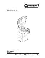
Layout.
Refer to Figure 4-1.
Functional description of the unit:
1.
Display
Refer to Chapter 4.1.
2.
Control panel
Refer to Chapter 4.2.
3.
Gauge arm
The gauge arm is a tool for measuring the rim.
4.
Flange
5.
Stub shaft
6.
Brake pedal
7.
Weight compartments
8.
Storage areas for cones or accessories
9.
Tilting frame and hood
10.
Storage area for Width Caliper
Refer to Figure 4-2.
1.
Mains switch (ON/OFF)
Содержание 1400
Страница 67: ...68...
Страница 68: ...69 Appendix Installation Instructions Annexe Instructions pour l Installation Anexo Instrucciones Instalaci n...
Страница 77: ...78 ACCU 1400 114 0 July 02...
Страница 78: ...ACCU TURN 1400 SPARE PARTS EXPLODED VIEWS Digital Wheel Balancer...
Страница 80: ...81 ACCU 1400 114 0 July 02...
Страница 81: ......
Страница 82: ......
Страница 83: ...84 ACCU 1400 114 0 July 02...
Страница 84: ...85 ACCU 1400 114 0 July 02...
Страница 85: ...86 ACCU 1400 114 0 July 02...
Страница 86: ...87 ACCU 1400 114 0 July 02...
Страница 87: ...ACCU TURN 1400 Rev A 2 14 05 WDC...


