


LIST O F FIGUR ES
IV
Figure 49: Measurements view, injected phase 1
................................................................................
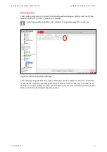
Figure 50: Blocking conditions of the circuit breaker truck in PCM600
........................................
Figure 51: Single line diagram, the circuit breaker is open and in the test position
Figure 52: Single line diagram, the earthing switch shutter is open
...............................................
Figure 53: Single line diagram, the earthing switch shutter is closed
............................................
Figure 54: Single line diagram, the circuit breaker is in the intermediate position
Figure 55: Blocking conditions of the circuit breaker in PCM600
...................................................
Figure 56: Single line diagram, the circuit breaker is closed and in the test position
Figure 57: Single line diagram, the circuit breaker is open and in the test position
Figure 58: Single line diagram, the circuit breaker is in the intermediate position
Figure 59: Single line diagram, the circuit breaker is closed and in the service position
Figure 60: Blocking conditions of the earthing switch in PCM600
.................................................
Figure 61: Single line diagram, the circuit breaker is open and in the test position
Figure 62: Single line diagram, the circuit breaker is in the intermediate position
Figure 63: Single line diagram, the earthing switch is closed
..........................................................
Figure 64: Example of Process bus application in medium voltage switchgear
Figure 65: Logic scheme of the busbar earthing truck interlock
....................................................
Figure 66: Logic scheme of the busbar earthing switch interlock
..................................................
Figure 67: Single line diagram, the circuit breaker is in the test position
.....................................
Figure 68: Single line diagram, the circuit breaker is in the intermediate position
Figure 69: Logic scheme of trucks interlock by the busbar earthing truck
..................................
Figure 70: Logic scheme of trucks interlock by the busbar earthing switch
................................
Figure 71: Single line diagram, the circuit breaker is in the test position
......................................
Figure 72: Logic scheme of CBFP
Figure 73: Single line diagram, the circuit breaker in the service position
....................................
Figure 74: Single line diagram circuit, the circuit breaker is closed and in the service position
Figure 76: Activating backup trip
Figure 77: Deactivating backup trip
Figure 79: Logic scheme of the Logic busbar protection
..................................................................
Figure 80: Single line diagram, the circuit breaker is in the service position
...............................
Figure 82: Activating START signal
Figure 83: Activating blocking mode
Figure 84: Deactivating START signal
....................................................................................................
Figure 85: Deactivating blocking mode
.................................................................................................
Figure 87: Logic scheme of Ith limiters trip
..........................................................................................
Figure 88: Single line diagram, the circuit breaker is in the service position
...............................
Figure 89: Single line diagram, the circuit breaker is closed and in the service position
Figure 90: Logic scheme of ARC trip
Figure 91: Single line diagram, the circuit breaker is in the service position
................................
Figure 93: Single line diagram, the circuit breaker is closed and in the service position
Figure 94: Activating OPERATE signal
....................................................................................................
Figure 95: Deactivating OPERATE signal
................................................................................................
Figure 97: Changing correction factors for amplitude
......................................................................
Figure 98: Changing correction factors for angle
...............................................................................
RJ45 test block (the plug, the lid and the socket)
.......................................
Figure 100: Low Voltage Compartment door of UniGear panel with ESSAILEC® RJ45 test
blocks
Содержание UniGear Digital
Страница 1: ...DISTRIBUTION SOLUTIONS UniGear Family UniGear Digital Commissioning and testing Guide...
Страница 2: ......
Страница 3: ...DISTRIBUTION SOLUTIONS UniGear Family UniGear Digital Commissioning and testing Guide...
Страница 6: ......
Страница 10: ......
Страница 12: ......
Страница 88: ...SECONDARY TEST SETUPS SECONDARY TESTING OF PROTECTION RELAYS 76 1VLG500017 C Figure 119 Measurements view...
Страница 96: ......
Страница 98: ...Visit us www abb com mediumvoltage Document Number 1VLG500017 Rev C...