


PRIM AR Y TESTING
CURRENT S ENSORS
1VLG5000 17 C
23
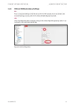
4.2.3
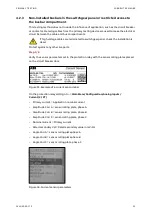
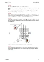
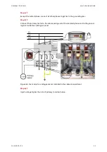
Non-installed busbars in the switchgear panel or restricted access to
the busbar compartment
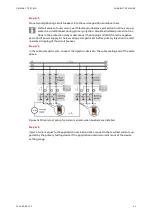
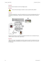
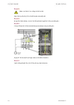
This testing method does not include the influence of application, such as the circuit breaker
or contactor. Metering cables from the primary testing device are used to make the electrical
circuit between the cable and bus compartments.
If high voltage cables are terminated to switchgear panel, check the installation is
dead.
Protect against any other live parts.
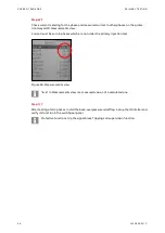
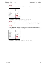
Step 1/6
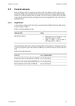
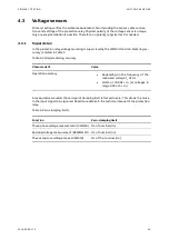
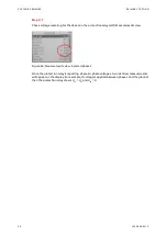
Verify the sensor parameters set in the protection relay with the sensor rating plates placed
on the circuit breaker door.
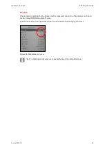
Figure 33: Example of a current sensor label
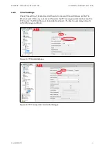
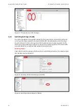
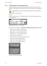
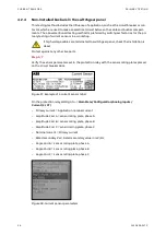
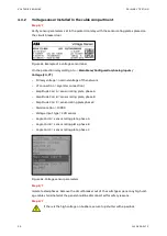
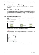
On the protection relay LHMI go to ->
Main Menu/Configuration/Analog inputs/
Current (3I, CT)
–
Primary current = Application nominal current
–
Amplitude Corr A = sensor rating plate, phase A
–
Amplitude Corr B = sensor rating plate, phase B
–
Amplitude Corr C = sensor rating plate, phase C
–
Nominal current = Primary current
–
Rated secondary Val = Rated secondary value in mV/Hz
–
Angle Corr A = sensor rating plate phase A
–
Angle Corr B = sensor rating plate phase B
–
Angle Corr C = sensor rating plate, phase C
Figure 34: Current sensor parameters
Содержание UniGear Digital
Страница 1: ...DISTRIBUTION SOLUTIONS UniGear Family UniGear Digital Commissioning and testing Guide...
Страница 2: ......
Страница 3: ...DISTRIBUTION SOLUTIONS UniGear Family UniGear Digital Commissioning and testing Guide...
Страница 6: ......
Страница 10: ......
Страница 12: ......
Страница 88: ...SECONDARY TEST SETUPS SECONDARY TESTING OF PROTECTION RELAYS 76 1VLG500017 C Figure 119 Measurements view...
Страница 96: ......
Страница 98: ...Visit us www abb com mediumvoltage Document Number 1VLG500017 Rev C...