


Operation, configuration and communication
42/14-39 EN
Sensyflow iG, Version 1.00
39
7.4.4
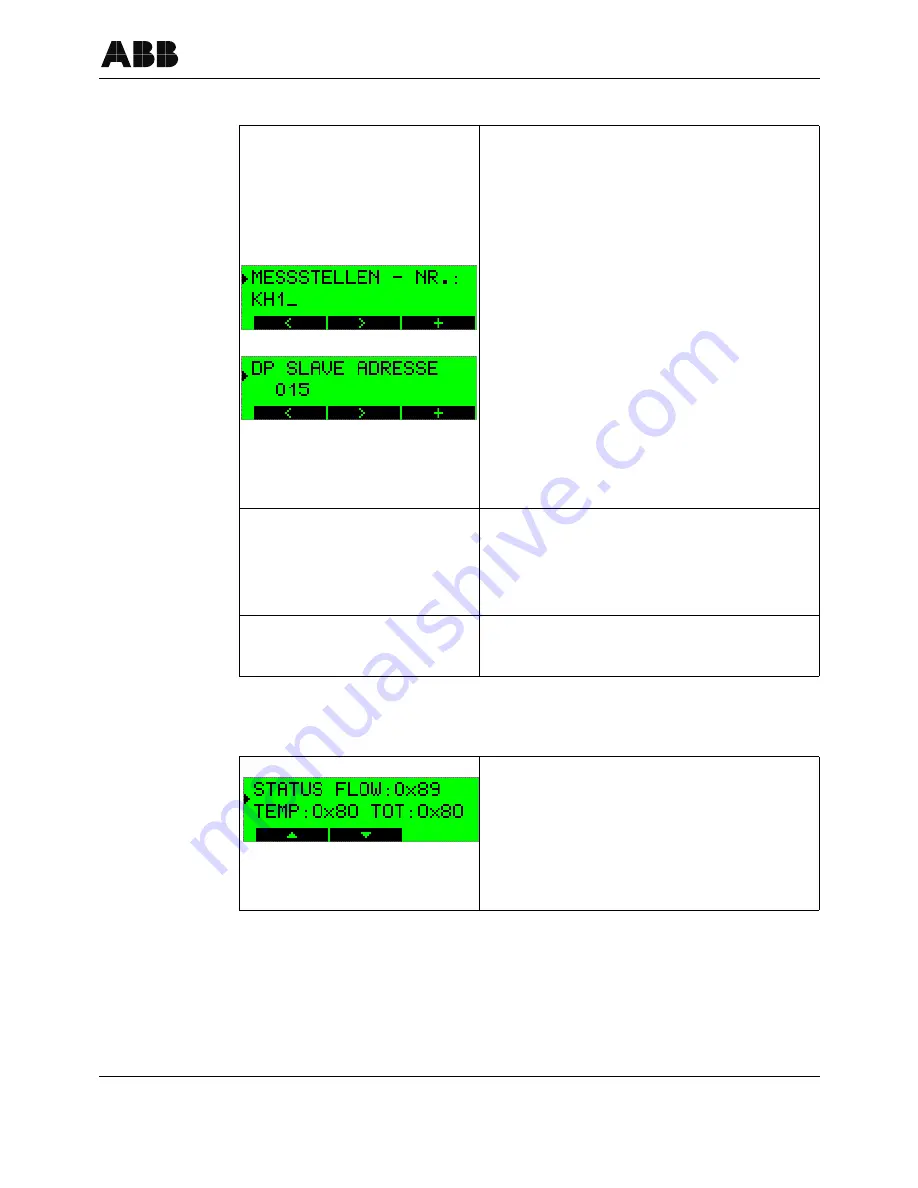
Entering and changing data
7.4.5
Status signals
The examples MEASURING POINT NO. and DP SLAVE
ADDRESS are used to demonstrate entering and chan-
ging data. Both entry masks are found in the PARAMETER
MENU that can be accessed by actuating the up/down AR-
ROW buttons from any display mode. The SERVICE or
SPECIALIST mode must have been set in order to make
entries and changes (see section 7.4.3).
After selecting the PARAMETER MENU, open it with the
ENTER button. The display shows MEASURING POINT
NO. and in the second line the set TAG number. With the
ENTER button you switch to change mode (see figure on
the left).
The data is entered by actuating the left/right ARROW but-
tons (cursor position) and the + button (setting the numeric
value or the desired character). To terminate the entry, the
cursor must be positioned to the right behind the entry
field. Only at this cursor position the + button becomes the
ENTER button again and can be used to save the entry
and exit the change mode.
The display switches back to the PARAMETER MENU
where you can make further configuration changes.
To save the entries and changes permanently you must
select the menu item SAVE CONFIG. in the PARAMETER
MENU and confirm with ENTER. If you do not save the
data the changes are lost during a hardware reset or in
case of a power failure.
The menus can only be left via the END..... MENU mask
by using the ENTER button.
In the SERVICE MENU and in different other locations of
the individual menus you can call up the hexadecimal sta-
tus signals of the measuring values FLOW, TEMP, and
TOT. (For explanations see sections 7.1.2.2 and 7.1.2.3)
Furthermore, eight diagnostic signal are available in the
SERVICE MENU, showing information about the device
status. (For explanation
see section 7.1.3 "Acyclic data
communication (DPV1)" on page 27
)


