2-10
C
HAPTER
2: I
NSTALLATION
The following sections describe the 16-port asynchronous module’s serial
connectors and the distribution options shown in Figure 2-5 and Figure 2-6.
These sections also tell you whether you can buy the option directly from
3Com or your network supplier, and they give recommended vendors and
part numbers.
Serial Connectors
A 16-port asynchronous module has two horizontally mounted 50-pin
female RJ-21 (Telco) connectors that support RS-232/RS-423 signals. Each
serial connector contains 8 ports, for a total of 16 ports per module, or 48
ports for a communications server with the full complement of three
modules. The communications server acts as a DCE device and can be
attached to a DTE device, such as a terminal, host, or printer, using a
straight-through cable. If you want to connect the server to a DCE device,
such as a modem, use a null modem cable.
For more information on 16-port asynchronous modules, refer to “16-Port
Asynchronous Modules”.
You can connect an extension or octopus cable to the serial connectors.
Fasten these cables to the serial connectors with the screw and strain relief
provided. For information on the cable strain relief mechanism, refer to “Cable
Strain Relief”.
For pin assignments of serial connectors, refer to Appendix A, “Pin
Assignments.”
Extension Cable
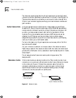
3Com recommends an extension cable with a 50-pin bottom-entry male
connector on one end and a 50-pin bottom-entry male or female connector
on the other end. Figure 2-7 shows this extension cable. Connect the
extension cable’s male connector to a serial connector on the 16-port
asynchronous module. Connect the cable’s remaining male or female
connector to an octopus cable or a patch panel.
Figure 2-7
Extension Cable
50-pin bottom-entry
male connector
50-pin bottom-entry
male or female connector
CS3000BookFile Page 10 Tuesday, October 15, 1996 5:12 PM


