
Chapter 10 Interfaces
ZyWALL USG Series User’s Guide
369
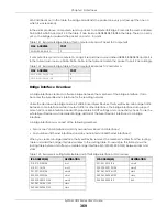
MAC address is not in the table, the bridge broadcasts the packet on every port (except the one on
which it was received).
In the example above, computer A sends a packet to computer B. Bridge X records the source address
0A:0A:0A:0A:0A:0A and port 2 in the table. It also looks up 0B:0B:0B:0B:0B:0B in the table. There is no entry
yet, so the bridge broadcasts the packet on ports 1, 3, and 4.
If computer B responds to computer A, bridge X records the source address 0B:0B:0B:0B:0B:0B and port 4
in the table. It also looks up 0A:0A:0A:0A:0A:0A in the table and sends the packet to port 2 accordingly.
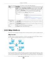
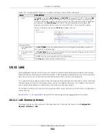
Bridge Interface Overview
A bridge interface creates a software bridge between the members of the bridge interface. It also
becomes the Zyxel Device’s interface for the resulting network.
Unlike the device-wide bridge mode in ZyNOS-based Zyxel Devices, this Zyxel Device can bridge traffic
between some interfaces while it routes traffic for other interfaces. The bridge interfaces also support
more functions, like interface bandwidth parameters, DHCP settings, and connectivity check. To use the
whole Zyxel Device as a transparent bridge, add all of the Zyxel Device’s interfaces to a bridge
interface.
A bridge interface may consist of the following members:
• Zero or one VLAN interfaces (and any associated virtual VLAN interfaces)
• Any number of Ethernet interfaces (and any associated virtual Ethernet interfaces)
When you create a bridge interface, the Zyxel Device removes the members’ entries from the routing
table and adds the bridge interface’s entries to the routing table. For example, this table shows the
routing table before and after you create bridge interface br0 (250.250.250.0/23) between lan1 and
vlan1.
Table 121 Example: Bridge Table After Computer A Sends a Packet to Computer B
MAC ADDRESS
PORT
0A:0A:0A:0A:0A:0A
2
Table 122 Example: Bridge Table After Computer B Responds to Computer A
MAC ADDRESS
PORT
0A:0A:0A:0A:0A:0A
2
0B:0B:0B:0B:0B:0B
4
Table 123 Example: Routing Table Before and After Bridge Interface br0 Is Created
IP ADDRESS(ES)
DESTINATION
IP ADDRESS(ES)
DESTINATION
210.210.210.0/24
lan1
221.221.221.0/24
vlan0
210.211.1.0/24
lan1:1
230.230.230.192/26
wan2
221.221.221.0/24
vlan0
241.241.241.241/32
dmz
222.222.222.0/24
vlan1
242.242.242.242/32
dmz
230.230.230.192/26
wan2
250.250.250.0/23
br0
241.241.241.241/32
dmz
242.242.242.242/32
dmz
Summary of Contents for USG110
Page 27: ...27 PART I User s Guide ...
Page 195: ...195 PART II Technical Reference ...
Page 309: ...Chapter 10 Interfaces ZyWALL USG Series User s Guide 309 ...
Page 313: ...Chapter 10 Interfaces ZyWALL USG Series User s Guide 313 ...
Page 358: ...Chapter 10 Interfaces ZyWALL USG Series User s Guide 358 ...
Page 373: ...Chapter 10 Interfaces ZyWALL USG Series User s Guide 373 ...


