Chapter 8 Monitor: Port
GS1900 Series User’s Guide
72
Powered Device (PD).
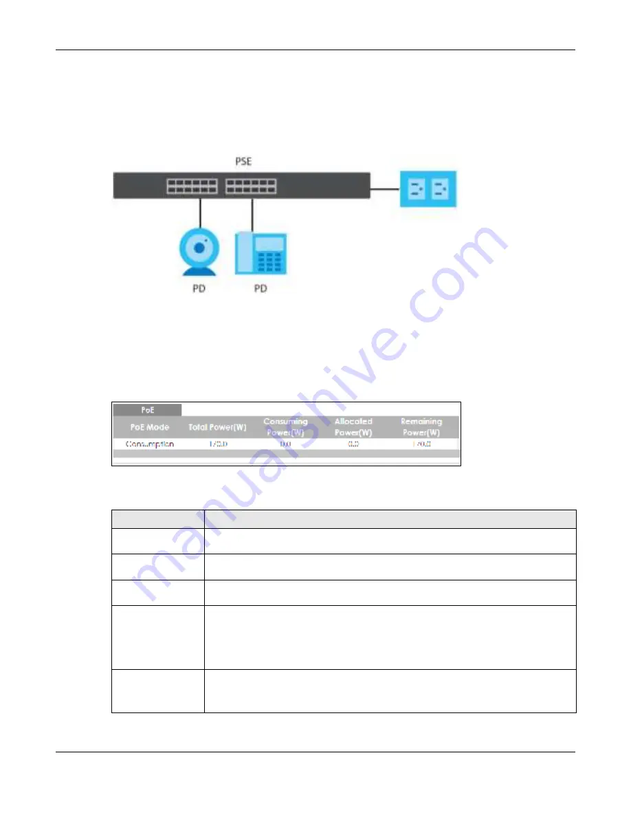
In the figure below, the IP camera and IP phone get their power directly from the Switch. Aside from
minimizing the need for cables and wires, PoE removes the hassle of trying to find a nearby electric
outlet to power up devices.
Fig ure 74
Powered Device Examples
You can also set priorities so that the Switch is able to reserve and allocate power to certain PDs.
Note: The PoE devices that supply or receive power and their connected Ethernet cables
must all be completely indoors.
To view the current amount of power that PDs are receiving from the Switch, click
Mo nito r
>
Po rt
>
Po E
.
Fig ure 75
Monitor > Port > PoE
Each field is described in the following table.
Table 29 Monitor > Port > PoE
LABEL
DESC RIPTIO N
PoE Mode
This field displays the power management mode used by the Switch, whether it is in
C la ssific a tio n
or
C o nsum ptio n
mode.
Total Power(W)
This field displays the total power the Switch can provide to the connected PoE-enabled
devices on the PoE ports. The total power of GS1900-10HP is 77 W and GS1900-8HP is 70 W.
Consuming
Power(W)
This field displays the total amount of power the Switch is currently supplying to the
connected PoE-enabled devices.
Allocated Power(W)
This field displays the total amount of power the Switch (in
C la ssific a tio n
mode) has
reserved for PoE after negotiating with the connected PoE devices. It shows
NA
when the
Switch is in
C o nsum ptio n
mode.
C o nsum ing Po we r (W)
can be less than or equal but not more than the
Allo c a te d Po we r
(W)
.
Remaining Power(W)
This field displays the amount of power the Switch can still provide for PoE.
Note: The Switch must have at least 16 W of remaining power in order to supply power to a
PoE device, even if the PoE device needs less than 16 W.
Summary of Contents for GS1900 Series
Page 16: ...16 PART I Use r s Guide ...


