User Manual 3PH HYD5000-HYD20000-ZSS
Rev. 1.1 16/03/2021
Identification: MD-AL-GI-00
Rev. 1. of 16/03/2021 - Application: GID
46/138
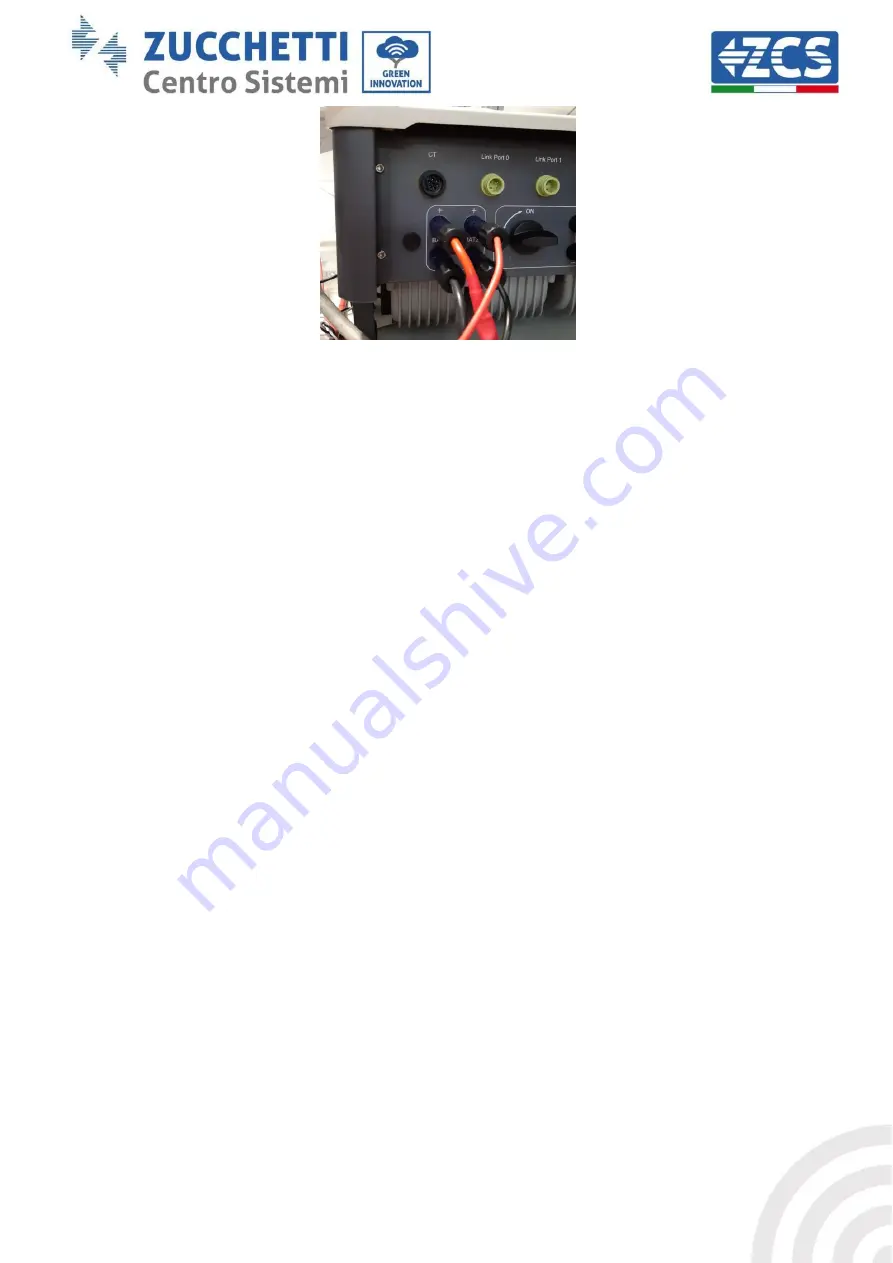
Figure 45 - Inverter-side DC power connection with two battery inputs populated
Identify the two battery towers by assigning the number 1 to the tower connected to channel 1 and
number 2 to the tower connected to channel 2.
Communication between the HV BOX and Battery Modules
The communication connections must be arranged for each tower as indicated in section 2.2. 2, using
communication cables between the battery modules:
CAN1-B of the HV BOX to CAN-A of the first battery
LINK of the HV BOX to LINK-A of the first battery
CAN-B of the first battery to CAN-A of the second battery
LINK-B of the first battery to LINK-A of the second battery
…
CAN-B of the second-last battery to CAN-A of the last battery
LINK-B of the second-last battery to LINK-A of the last battery.
HV BOX – Inverter communication
In the case of two battery towers:
1.
Battery Tower 1
Set address to ADD=00000000
2.
Battery Tower 2
a.
All pins in the OFF position, except for pin 1 and pin 7, which must be in the ON
position (ADD=10000010).
A cable from the CAN2-A input of the HV BOX of tower 2 must be connected to the CAN2-A input of the
HV BOX of tower 1; finally, the Inverter/HV BOX communication cable must be inserted in the CAN2-B
port of the HV BOX.


