User Manual 3PH HYD5000-HYD20000-ZSS
Rev. 1.1 16/03/2021
Identification: MD-AL-GI-00
Rev. 1. of 16/03/2021 - Application: GID
33/138
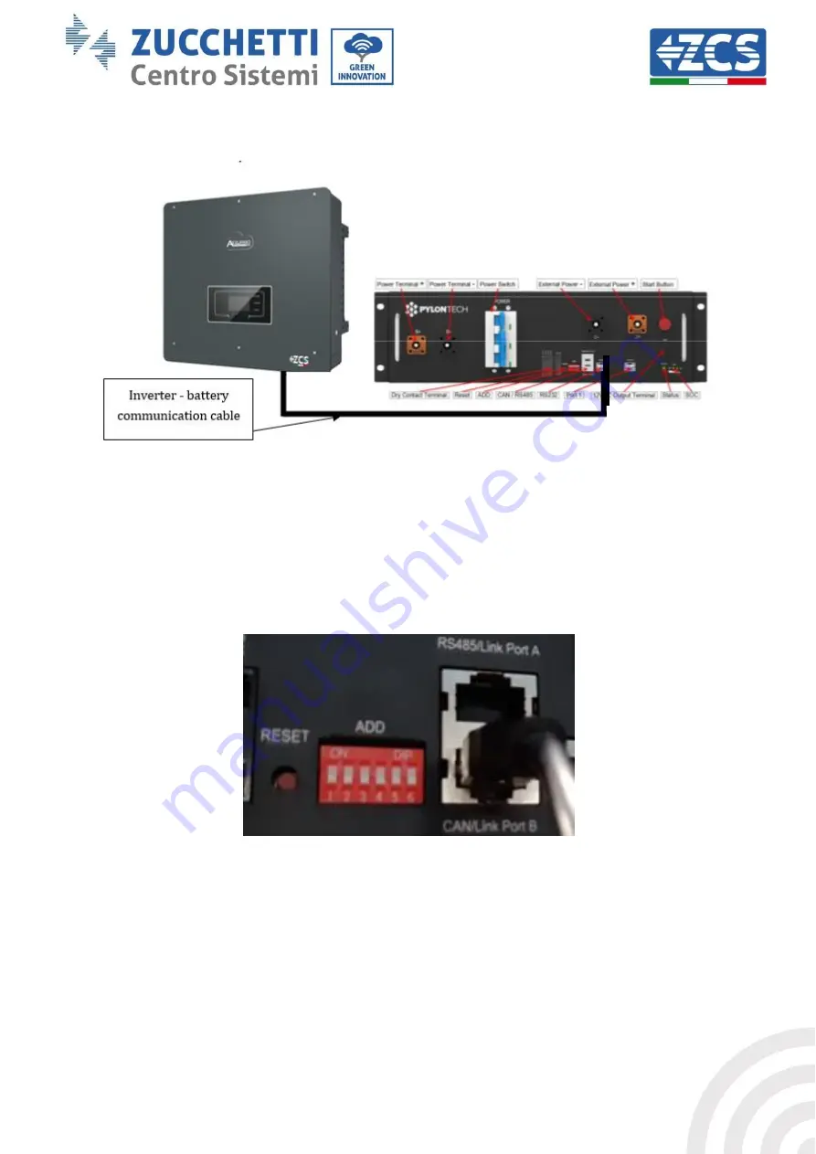
BMS and Inverter communication
Figure 26 - Hybrid inverter and BMS communication connection
The position of the DIP switches in case of a single tower requires moving all the pins down, this
means the address equals 000000.
Figure 27 – 000000 battery address
For communication between the battery and inverter, use the black communication cable supplied,
which has the BAT and INV labels on the RJ45 end. On the BMS side, insert the end labelled BAT in link
port B. The other end, labelled INV, must be cut leaving only the wires connected to pins 2 (orange
wire), 4 (blue wire) and 5 (white-blue wire) in the appropriate communication counterpart of the
hybrid inverter.


