background image

121 


5.16.


Speed Reducer 


Maintenance instructions 

Rotary reducer lubricating oil capacity ----------------------- 0.5 liters 
Travel reducer lubricating oil capacity  ---------------------------1 liter (each side) 
Check lubricant oil level and refueling -----------------------Every 250 hours of operation 
Change lubricating oil ------------------------------------- 1000 hours per operation 
Check  reducer  connecting  bolt  tightening  torque  --------------------  500  hours  per 
operation 
 

WARNING:  The  oil  in  the  reducer  will  become  hot  soon  after  the 
machine  is  running.  When  the  engine  is  turned  off,  the  travel  reducer 
and  oil  are  still  hot  and  can  cause  serious  burns.  Before  starting 

operation, you must wait for the oil to cool down. Loosen the air vent plug by two to 
three clicks to relieve the air pressure before removing the plug. It is dangerous to 
remove the screw plug too fast. 


5.16.1.


Traveling reducer 

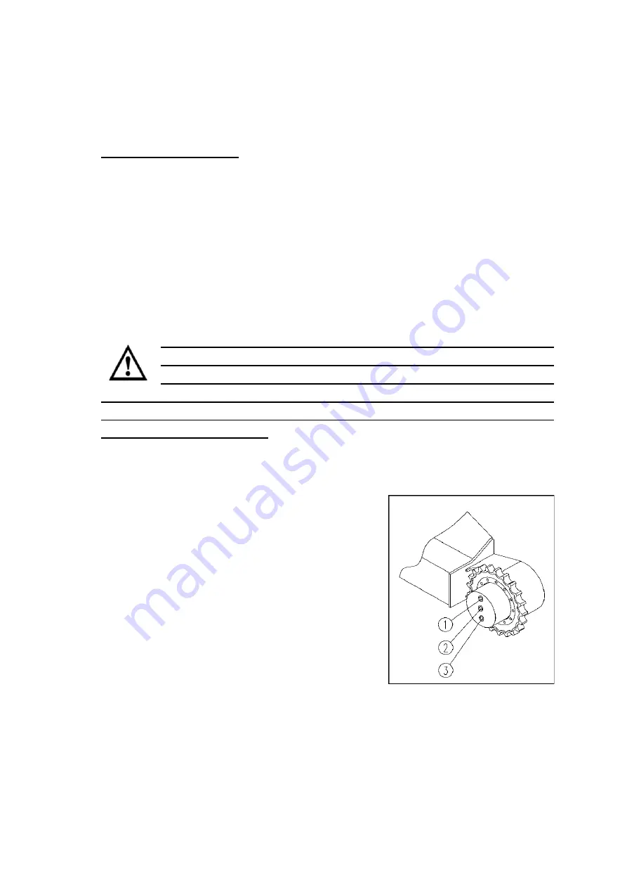
Check  the  lubricating  oil  level  of  the  travel 
reducer and add oil 
Check every 1000 hours of operation. 
1)


 Prepare an Allen wrench. 

2)


Park the excavator on a level surface. 

3)


Rotate  the  travel  gearbox  so  that  the  three 
plugs outside of the gearbox are perpendicular 
to the ground, then stop the machine. 

4)


Open  the  screw  plug 

  and  check  the 

position of the lubricant level, which should reach the lower edge of the screw 
plug hole. 

Summary of Contents for YC20SR

Page 1: ...HYDRAULIC EXCAVATOR YC20SR YC18SR U20 U18 OPERATION MANUAL GUANGXI YUCHAI HEAVY INDUSTRY COMPANY LIMITED ...

Page 2: ...understand the instructions for the safe operation of the machine Understand and be familiar with all safety signs on the machine Make sure that nobody unrelated to the job is at the work site Operators should have been trained in the safe operation of the machine before operating the machine at the work site You are responsible for complying with relevant laws and regulations and following Yuchai...

Page 3: ...2 Working paragauges 9 1 7 3 Traveling mechanism 10 1 7 4 Hydraulic system 10 1 7 5 Electric system 10 1 7 6 Working condition 10 1 7 7 Interference 11 2 Safety rules 12 2 1 General safety rules 12 2 2 Safety labels and instructions 13 2 3 Safety equipment 13 2 4 Security Signs 14 2 4 1 Classification of safety signs 14 2 4 2 Location of safety Signs 15 2 4 3 Safety signs and descripton 16 2 5 Wor...

Page 4: ... 40 3 2 Safety locking components 41 3 3 Switch assembly 42 3 4 Electronics Controls 43 3 4 1 Key start switch operation 43 3 4 2 Cigarette lighter 44 3 5 Monitor 44 3 6 Work device s and Swing Controls 45 3 7 Travel control 46 3 8 Throttle handle and stop handle 46 3 9 Driver s Seat 47 3 10 Seat belt 47 4 Operation Instructions 49 4 1 Preparation before operating the machine 49 4 2 Engine Operati...

Page 5: ... control 61 4 7 3 Boom control 61 4 7 4 Bucket control 61 4 7 5 Boom deflection control 61 4 7 6 Dozer blade control 61 4 8 Working on slope or water 62 4 8 1 Slope 62 4 9 Getting out of the Muddy Environment 63 4 10 General Operations instruction 64 4 10 1 Backhoe operation 64 4 10 2 Loading operation 64 4 10 3 Trenching operations 65 4 10 4 Backfilling or grading 65 4 10 5 Shake off the soil stu...

Page 6: ...torage of the machine 76 4 17 1 Preparation before storage 76 4 17 2 During storage 77 4 17 3 Returning to work after storage 77 4 18 Causes of technical failures and solutions 78 5 Maintenance 85 5 1 General knowledge of maintenance 85 5 1 1 New machine break in 85 5 1 2 Working in dusty sites 85 5 1 3 Oil and Filter 85 5 1 4 Timer Readings 86 5 1 5 Use genuine parts 86 5 1 6 Waste disposal 86 5 ...

Page 7: ...5 9 Engine Fuel System 98 5 9 1 Oil level check and refueling 98 5 9 2 Drain water and contaminants from the tank 99 5 9 3 Cleaning the fuel tank 99 5 9 4 Check the injection pressure 99 5 9 5 Vent air from fuel circuit 100 5 9 6 Changing the fuel filter 100 5 9 7 Replace the fuel filter 101 5 10 Engine Cooling System 101 5 10 1 Check the coolant level 102 5 10 2 Check the condition of the rubber ...

Page 8: ...d clean the oil suction filter 111 5 14 4 Vent air from the hydraulic system 113 5 14 5 Replace the return oil filter element 115 5 14 6 Replace the pilot oil filter element 116 5 15 Battery 117 5 15 1 Storage of battery 118 5 15 2 Charging of the battery 118 5 15 3 Installation of the battery 119 5 15 4 Battery maintenance 120 5 16 Speed Reducer 120 5 16 1 Traveling reducer 121 5 16 2 Replace the...

Page 9: ... 135 6 5 Quick coupler 136 6 6 Grab Bucket 137 6 6 1 Installation of grab bucket 137 6 6 2 Operation of the grab bucket 138 6 6 3 Operation precasutions of the grapple 138 6 6 4 Maintenance of the grapple 140 6 7 Drilling device 140 6 7 1 Installation of drilling device 140 6 7 2 Operation of the drilling unit 141 6 7 3 Precautions for the operation of drilling device 141 6 8 Backhoe bucket with s...

Page 10: ...y Please entrust the overhaul and adjustment of the machine to Yuchai Heavy Industry s dealer or service station and use original parts and spare parts provided by our company If you use non original parts or components they may not have an obvious effect on the machine at the time but may cause problems later Yuchai Heavy Industry will not undertake the warranty service even if the machine breaks...

Page 11: ...n of the machine you can view it in the position shown in the picture Machine information Nameplate is located on the right front side of the upper machine Engine Information Machine operation information engine timer is located on the monitor in the right joystick box ...

Page 12: ...ne You can provide them to Yuchai when you need to purchase spare parts or request relevant information Please record these numbers and keep them together with the product certificate If your machine is stolen you can submit them to police MODEL SERIAL NUMBER ENGINE SERIAL NUMBER DEALER ...

Page 13: ...4 1 3 Machine directions The front back left right top and bottom on this manual refer to each direction of the illustrated pictures Up Down Right Front Back Left ...

Page 14: ...vel Reducer 3 Arm 14 Driving Roller 4 Arm Cylinder 15 Carrier Roller 5 Boom Cylinder 16 Chassis 6 Boom 17 Slew Ring 7 Cab 18 Idler 8 Hydraulic Tank 19 Boom Swing Cylinder 9 Fuel Tank 20 Dozer Blade Cylinder 10 Rear Panel 21 Boom Swing Knuckle 11 Upper Platform 22 Dozer ...

Page 15: ... are caused by negligence of basic safety precautions and hazard prediction By anticipating the conditions where hazards may occur accidents can be prevented Therefore it is important to be aware of the location and type of hazards In order to do so operators must have the required training skills and tools Read and understand all safety precautions WARNINGs and accident prevention methods describ...

Page 16: ...ate unsafe practices that may result in injury We cannot predict all hazards of operation inspection maintenance and repair in all environments Therefore the WARNINGs indicated in this manual and on the machine do not cover all situations During operation inspection maintenance and repair operations that are not covered in this manual user is requested to follow the necessary safety precautions It...

Page 17: ...Working device height to the top of boom mm 1150 D Overall width mm 1080 E Over all height transportation status mm 2345 F Ground clearance of platform mm 465 G Min ground clearance of chassis mm 145 H Tail slewing radius mm 700 I Track grounding length mm 1230 J Track length mm 1600 K Gauge mm 850 1170 L Width of chassis mm 1080 1400 M Width of track mm 230 O Height of engine hood mm 1265 P Lengt...

Page 18: ...h mm 2310 DD Max vertical digging depth mm 1920 EE working device Min slewing radius mm 1690 FF Max digging radius on ground level mm 4060 GG Max digging radius mm 4125 HH Max lifting height of dozer blade mm 245 JJ Maximum bulldozing depth mm 245 Max digging force of bucket KN 15 5 Max digging force of arm KN 8 5 offset boom Max left swing angle o 55 offset boom Max right swing angle o 65 ...

Page 19: ... speed 2 1 7 4 Hydraulic system Load sensing hydraulic system Max hydraulic flow rate 61 6L min 2200 rpm Working pressure 24 Mpa LS 21 5 Mpa load compensated pressure difference 2 5 Mpa Slewing pressure 9 Mpa Auxiliary pipe 1 Auxiliary pipe 2 pressure 21 Mpa Pilot pressure 3 5 Mpa Oil return filter 10 μm Oil intake filter metal filter 1 7 5 Electric system Voltage 12V Battery 45 AH 1 7 6 Working c...

Page 20: ...he boom cylinder and damage to the machine body The following are all the non standard attachment work device s that we offer Buckets Bucket attachments mounted directly on the boom Bucket attachment with quick connector Bucket attachment mounted on quick couple Rock breaker Directly mounted on the boom Crushing hammers mounted on quick couple Auger Auger mounted on the boom directly Auger mounted...

Page 21: ...rform any actions prohibited by the instructions in this book The excavator should be operated and maintained by trained and qualified personnel Before starting to work check all functions of the machine If the machine is not working properly stop immediately to find out the cause of the problem and work only after solving the problem The inspection maintenance and repair should be carried out in ...

Page 22: ... or CAUTION The following are their corresponding explanations DANGER Indicates that if not avoided the consequences of the hazard will result in death or serious injury and is only applicable to the few occasions when the greatest danger exists WARNING Indicates that the consequences of the potential hazard may result in death or serious injury if not avoided CAUTION Indicates that the consequenc...

Page 23: ...read and understand the manual and the WARNING signs on the machine and follow the relevant procedures Check the signs before starting the machine every day to make sure they are clean and legible When cleaning the signs use only cotton cloth water and soap Do not use organic solvents and gasoline etc If the sign is broken lost or unreadable replace it If the marker is located on a part that needs...

Page 24: ...n has a diagram and corresponding explanatory text and is used where the graphic does not adequately convey the safety message 2 4 2 Location of safety Signs The sign shown is only the safety signs other type of signs logos are described in later sections ...

Page 25: ...tay away from the working device Moving work equipment can cause injury Keep a safe distance from the area where the work device is working Warning signs Fuel oil inlet left signs Lifting combination signs Warning signs Safety switch signs ...

Page 26: ...17 Hydraulic oil refiling sign Swing center Control signs Throttle sign Warning sign Tail signs Safety sign Warning sign ...

Page 27: ...18 Warning sign Reading manual sign Machine Lift Points Lubrication oil refill sign High temperature sign Stop engine sign ...

Page 28: ...19 Warning sign Maintenance warning Swing lock sign ...

Page 29: ... before you begin work WARNING Contact your local utility service system and department before starting an excavation project 13 When working in a building find out the overhead room porches aisles etc and the load bearing capacity of floors and ramps Ensure adequate ventilation when operating indoors What you don t know can hurt you 14 Know the ground clearance the exact distance between the elec...

Page 30: ... 6 Safe Operations WARNING It is strictly forbidden to carry or lift people with the excavator WARNING Before operating the machine you must fasten the safety belt sound the horn and make sure no one is around the work area before starting to work 2 6 1 Start the engine Safety rules for starting the engine 1 Before starting the engine sound the horn to warn 2 No one other than the operator is allo...

Page 31: ...ition with the working device in the same direction as the dozer If the working device is in the opposite direction of the dozer the operation will be reversed 2 Sound the horn before traveling and slewing to warn people in the working area 3 The excavator must travel and operate on solid ground of more than 1 5 times its width 4 Before backing up and slewing if there is visually blocked area make...

Page 32: ... safe distance from people buildings or other machines 5 When traveling through underpasses under bridges or under power lines and other places of limited height use hand signals to direct And be careful to maintain safe distance 6 Always lock the platform when traveling up and down slopes 7 When passing over bridges or buildings or supports make sure that they are sufficient to support the weight...

Page 33: ...l the platform should be locked the driving wheel should be in the direction of the slope the arm and boom should be fully extended and the bucket teeth should be 20 30cm away from the ground and the slope should be downhill at low speed 5 Do not turn on the slope or cross the slope Be sure to go down to a flat place to change the position of the machine and then go up the slope again 6 When worki...

Page 34: ...lowing If the engine stalls on a slope lower the bucket and dozer to the ground immediately and put all handles in the neutral position then restart the engine Even if the engine stops for a short time on a slope lower the bucket and dozer to the ground and pull all handles to the neutral position and place a secure obstacle at the lower end of the tracks 10 It is strictly forbidden to travel on t...

Page 35: ...rious injury or equipment damage So before operating you should build up a strong platform with soil that can keep the machine level 2 6 5 Safe excavation operations WARNING The operator must be familiar with the functions of each operating lever WARNING Improper use of the excavator can cause tipping or skidding so memorizing this section to ensure your personal safety 1 Remove any unrelated pers...

Page 36: ...the machine Always operate the hydraulic cylinder with a small margin 8 When digging deep make sure the hoses under the arm or bucket do not touch the ground 9 When operating the machine avoid touching the boom arm bucket and cab with foreign objects 10 When the machine is swinging avoid touching the engine hood and rear counterweight 11 When lowering the arm try not stop suddenly 12 Do not dig in...

Page 37: ...driver as this will overload the rear structure of the machine This will not only damage the machine but is also very dangerous 16 Do not overuse the bucket to level the road otherwise the parts will be overloaded and the machine will be damaged 17 Do not use the falling force of the machine for digging as this may damage the machine ...

Page 38: ...se actions can damage the working device 19 Do not dig into the ground with the bucket and use the traveling force to excavate as this will cause the rear of the machine to be subjected to excessive forces 20 Do not excavate under the overhanging part as there is a risk of falling rocks or of the overhanging part collapsing and hitting the machine ...

Page 39: ... shifted on uneven ground tracks are uneven or more than half of one track is overhanging 2 When the contact surface of one track is loose and the other is solid 3 When there is a cavern or a mud pit under one side of the machine 4 When traveling on a slope with a longitudinal slope greater than 25 and unloading heavy loads in the downhill direction 5 When traveling on a slope with a transverse sl...

Page 40: ...d it is strictly forbidden to mix people and machines When loading and unloading the excavator It is strictly forbidden to have any personnel and articles that may hinder the loading and unloading within the radius of the crane boom including the lifted object When loading and unloading the excavator there must not be any personnel and other articles that may hinder the loading and unloading withi...

Page 41: ...intenance work on the machine The excavator must be stopped on a firm level surface Once the excavator is parked the bucket must be lowered to the ground the engine must be run at idle speed for three minutes before shutting down the machine and removing the key Release all hydraulic system pressure When stopping on a slope as a last resort provide adequate barriers in the downward direction of th...

Page 42: ...e sure to operate in compliance with environmental regulations 2 6 9 Fire Explosion and Poisoning Prevention Avoid touching the electric wire when the excavator is transporting traveling and digging otherwise it may lead to serious casualties Excavator electrical appliances and wiring should be checked frequently If it is found to be banged up damaged or aged it must be replaced in time to prevent...

Page 43: ...l line To prevent fires caused by hydraulic lines Check that all hose and tube clamps shields and cushions are securely fastened in place If they are loose they might vibrate and rub against other parts during operation causing damage to the hoses and high pressure oil to spurt out resulting in fire hazards or serious injuries The battery should be kept away from the fire source and avoid high tem...

Page 44: ...kin are splashed with sulfuric acid flush with plenty of water and seek medical attention immediately Turn the key switch to the OFF position before handling the battery Check the electrolyte level with a flashlight and turn off the engine when doing so Expansion at the end of a sealed battery indicates that the battery has frozen Do not charge the battery or jumper start the engine when the batte...

Page 45: ...so before charging remove the battery from the lower body put it in a well ventilated place and remove the battery cover Tighten the battery cover securely ATTENTION When repairing the electrical system or performing welding operations remove the negative terminal of the battery to prevent the flow of current 2 6 11 Hydraulic system A Safety rules for high pressure oil There is always pressure ins...

Page 46: ...without isolating the hydraulic oil lines hoses If any damage is found to the hose stop the operation immediately and contact your Yuchai dealer Replace the hose if the following problems are found 1 Damaged or leaking hydraulic hose fittings 2 Worn or broken cladding or reinforcement wire exposed 3 Swelling of the cladding in some places 4 Twisted or crushed movable parts 5 Impurities in the pack...

Page 47: ...rn the start switch to the ON position and operate the lever in each direction working device travel Swinging to relieve internal pressure E Safe operation of the accumulator WARNING The accumulator is a high pressure nitrogen filled component and improper use may cause an explosion or other hazard The accumulator must not be disassembled drilled welded etc Keep the accumulator away from fire and ...

Page 48: ... key of the starter switch to the ON position again to allow current to flow in the circuit 4 Set the safety lockout control lever to the free position then operate the levers and attachment control pedal forward backward left and right at full stroke to release the pressure in control lines 5 Set the safety lockout lever to the locked position to lock the joystick and attachment control pedal ...

Page 49: ... Consoles 1 Main power switch 5 Right attachment pedal 9 Left attachment pedal 2 Throttle 6 Travel control pedal 10 Pilot system lock 3 Dozer lever 7 Left travel pedal 11 Left joystick 4 Swing Lock 8 Right travel pedal 12 Right joystick 13 Seat ...

Page 50: ...work device platform Swinging etc cannot work except for the left and right travel control After pushing the pilot safety locking handle forward and pressing it to the bottom and putting down the left operation box the pilot system will be connected with the oil pressure source and the machine can work normally Platform locking mechanism optional WARNING The platform locking mechanism is an import...

Page 51: ...itch the side with the switch sign is on and the other side is off 3 Middle Frame 4 Beacon switch Press the rocker switch the side with the switch sign is on and the other side is off 5 Fast travel switch Press the toggle switch the travel motor is in high speed and low torque travel state 6 Deflection switch or on the pilot handle Press the rocker switch and operate the left pilot handle to opera...

Page 52: ...er switch the air heater is working 10 Cover plate 3 4 Electronics Controls 3 4 1 Key start switch operation Stop the electrical system is off Work positon ON the electrical system is on Preheating the engine starts to preheat and intake air at this time the preheating indicator light is on It should be ATTENTIONd that the warm up time should not exceed 30 seconds This position can be automaticall...

Page 53: ...44 3 4 2 Cigarette lighter 3 5 Monitor ...

Page 54: ...eft B Right joystick Boom is lowered when pushing forward and retracted when pulling back Bucket bucket is turned outward when joystick turn right and turned inward when when joystick turn left slewing or offset boom function selection joystick button switch Both slewing and offset boom function are operated by right joystick Default setting is slewing action Press button 1 to execute the offset b...

Page 55: ... the auxiliary work device 3 7 Travel control Directional control The left and right travel levers control the left and right tracks of the machine Maneuver single lever can control one side of the track to turn the machine 3 8 Throttle handle and stop handle 1 Throttle Handle Push the engine throttle handle forward to increase the throttle Before the engine stops pull the throttle handle back to ...

Page 56: ...t to confirm the seat is secured 3 10 Seat belt WARNING The seat belt is an important part of the safety system The seat belt must be fastened before operation If the seat belt is not fastened the cab or machine may crush your body and cause injury if the machine tips over WARNING Before using the seat belt check the installation of the seat belt for any abnormalities If the seat belt is worn or d...

Page 57: ... adjust the length of the harness and insert the it firmly into the buckle Gently pull the seat belt and check that it is properly locked 2 Remove the seat belt Press the red button on the buckle and remove the clip from the buckle to remove the seat belt ...

Page 58: ...d the engine radiator and battery 7 Check whether the hydraulic device oil tank hoses and joints are leaking oil you can check whether there are obvious oil stains on the parking ground 8 Check whether the lower frame parts tracks drive wheels guide wheels etc are damaged and whether the bolts are loose The frame and platform bolts are not loosened 9 Check that the instruments and monitors are not...

Page 59: ... 4 Check that there are no cracks excessive wear or gap in the working device oil cylinder connecting rod hydraulic hose If abnormalities are found replace and repair 5 Check whether the hydraulic device hydraulic oil tank hose and joint are leaking oil 6 Check the lower body tracks sprockets guide wheels etc for damage wear loose bolts or oil leaks 7 Check whether the instrument display is normal...

Page 60: ...ttery electrolyte freezes do not charge the battery or start the engine with alternative power source Doing so will put the battery at risk of catching fire Before charging or starting the engine with alternative power source allow the battery electrolyte to thaw and check the battery electrolyte for freezing and leaks before starting Before starting the engine insert the key into the starter swit...

Page 61: ...etween two starts should not be less than 30 seconds if the engine cannot be started three times in a row check whether the engine systems are normal WARNING 1 Do not turn the key while the engine is running It will damage the engine 2 Do not start the engine while towing the excavator 3 Do not start the engine by short circuiting the starter motor circuit 4 2 2 1 Starting the engine with the jump...

Page 62: ...th a safe distance 3 When connecting the jumper cable turn the key switch of the normal machine and the defective machine to the OFF position Otherwise there is a danger of the machine moves when the power is turned on 4 When installing the jumper cable be sure to first connect the positive when removing the auxiliary cable you should first disconnect the ground or negative cable 5 When removing t...

Page 63: ... the bucket cylinder to the end of its stroke to warm up the hydraulic oil at full load but not more than 30 seconds at a time Repeat until the oil temperature requirement is reached B Check after starting the engine 1 Check if the indicator lights are off 2 Check oil lubricating oil fuel and water leaks 3 Check the sound vibration heating smell and instruments of the machine for any abnormalities...

Page 64: ...the engine room for foreign articles Remove confetti and debris to avoid fire 4 Remove the mud on the chassis 4 3 Enter and exit the machine 1 Make sure your hands are firmly on the handrail at the cab door 2 Step firmly on the tracks 3 When getting on and off the machine do not use the control handle as a handrail to grip 4 Before getting on or off the machine make sure that there is no mud greas...

Page 65: ...round bearing capacity etc 2 Sound the horn before starting the excavator 3 It is strictly forbidden to start and operate the machine with the driver not in the cab 4 The excavator must travel and operate on solid ground with a width of more than 1 5 times of that of the machine 5 When traveling through underground passages bridges or under high voltage power lines ensure that there is signalman t...

Page 66: ...ction when traveling at high speed can be dangerous 1 Do not switch the joystick suddenly otherwise it will cause sudden start 2 Avoid abruptly changing the joystick from forward to reverse or from reverse to forward 3 Avoid sudden switching of the joystick such as a sudden stop from high speed or release the joystick 4 4 2 Preparation for traveling 1 Put down the platform locking pin to lock the ...

Page 67: ...l speed could be abnormal when the machine is not warmed up thoroughly Also if the chassis is clogged with dirt and the machine is not running properly remove the dirt and mud 4 4 4 Travel backward 1 Lower the left control box raise the working device and lift it 40 to 50cm off the ground 2 Operate in the opposite way to forward 4 4 5 Stop the machine Put both levers in the middle position to stop...

Page 68: ...before turning 4 5 1 Turning when the machine is stopped When turning to the left When traveling forward push the right traveling lever forward and turn the machine to the left When traveling backward pull back the right travel lever and turn the machine to the left When turning to the right operate the left travel lever in the same way Spin turn When turning left in place pull the left travel lev...

Page 69: ...stick The working device is operated by the left and right joysticks The left joystick operates the boom and swing if equipped with a boom deflection selection switch the left joystick can also control deflection The right joystick operates the arm and bucket When the joystick or dozer lever is released they automatically return to the neutral position and the working device or dozer stops If the ...

Page 70: ...l The right joystick maneuver to the right to rotate out the bucket and to left to rotate it in 4 7 5 Boom deflection control Select the deflect mode on the joystick first Operate the left joystick to deflect the boom 4 7 6 Dozer blade control Dozer blade lever push down to turn dozer downward and pull up to lift the the dozer up Attention Arm control may lag this is not a mechanical problem Becau...

Page 71: ...eforehand When working on a slope turning or operating the working device can cause the machine to lose balance and tip over so avoid doing so When the bucket is loaded it is very dangerous to turn in the downhill direction so build a platform on the slope with soil so that the machine can be balanced during operation Do not go up or down steep slopes as there is a risk of the machine tipping over...

Page 72: ...ne side of the tracks is stuck ATTENTION When lifting the machine with working device be sure to keep the bottom of the bucket in contact with the ground Do not use bucket teeth to push The angle between the arm and boom should be 90 to 110 degrees When only one side of the track is stuck in the mud lift the track with the bucket then put a board or log under it and drive the machine out If necess...

Page 73: ...e to an angle of 30 toward the machine This may vary depending on the digging depth but try to operate within this range rather than operating the cylinder to the end of its stroke ATTENTION It is best to excavate hard rocky ground after it has been smashed by other means This will not only reduce the damage to the machine but is also more economical 4 10 2 Loading operation It is more efficient t...

Page 74: ...ntion 1 Do not touchpower lines in the air 2 Check the under ground utility lines or pipe lines before digging 3 In case of electric shock accident the driver should not leave the seat and warn others not to approach Drive the machine to a safe place and leave the cab after power off 4 10 4 Backfilling or grading In order to fill the ditch the direction of excavator travel should be perpendicular ...

Page 75: ... when using the dozer 1 The dozer should only be used for moving soil not for digging as this may damage the dozer or the track system 2 The dozer cant carry heavy objects that is too big or unstable center of gravity otherwise the dozer or the tracks will be damaged 3 The dozer must not hook on any object while traveling otherwise it will damage the dozer or the track system 4 When lifting the ma...

Page 76: ...clearly Start the excavator and face the bucket manipulate the arm until the hole between the arm and the bucket is aligned Insert a steel rod with diagauge 30 mm into the hole 1 Lift the boom and arm so that the bucket hangs vertically Operate the arm cylinder so that the hole in the connecting rod is aligned with the hole in the bucket Install the shaft 2 remove the rod 1 and install the shaft 3...

Page 77: ...e serious injury or accident Therefore before standing up from the seat always lift up the left control box and keep the machine in a locked position Parking the machine 1 Place the left and right travel levers in the neutral position Stop the machine 2 When the engine is working under heavy load do not stop immediately let it run at low speed for 1 2 minutes to clear overheating before stopping 3...

Page 78: ...od the engine hood might pop up and hurt people 4 15 Loading and unloading and transportation 4 15 1 Safety rules 1 Run the engine at low speed and operate the machine slowly when loading unloading 2 Do not load unload the machine when it is in automatic warm up state 3 If the automatic warm up is canceled during the loading unloading operation the speed will change suddenly 4 Loading unload the m...

Page 79: ...center of gravity may change suddenly and there is a risk of losing balance Therefore travel slowly when crossing this area 11 When turning the upper on the transport vehicle the transport vehicle is unstable Therefore retract the work device and turn it slowly 12 The wheels of the transport vehicle should be wedged when the excavator is getting on or off 13 Use wooden wedges to keep the excavator...

Page 80: ...mp operate only the travel lever not any other lever or pedal 6 Stop the machine and extend the arm position B in the diagram so that the front part of the excavator tracks tilts down onto transport vehicle make sure not to let the work device touch the body of the transport vehicle while the machine is tilted down 7 Lower the arm and drop the bucket on the floor lower the dozer and stop the machi...

Page 81: ... rope Take special care to secure the machine so that it does not slide to one side 4 15 4 Unloading from the transport vehicle 1 Load and unload on a firm level surface and maintain a safe distance from the edge of the road 2 Apply brakes to the transport vehicle and place pads under the tires to ensure that the vehicle does not move 3 Install a ramp between the transport vehicle and the machine ...

Page 82: ... Safety rules 1 Do not lift the machine when there are people on the machine 2 Be sure that the wire rope used to lift the machine is strong enough to carry the weight of the machine 3 Do not lift the machine in any position other than the one provided in the following procedures otherwise there is a risk of tipping over 4 Do not lift the machine with the superstructure turned to the side Before l...

Page 83: ...fting hole is labeled with a lifting hook symbol and pass the wire rope between the drive wheel and the first supporting wheel 5 Select the lifting position of the wire rope so that it is directly in the center of gravity of the machine the center of gravity of this model is above near the center of rotation as shown in the picture above 6 When lifting check whether there are leakage from the hydr...

Page 84: ...ling system Before operating the machine in cold weather check the coolant and adjust the proper mixing ratio Use antifreeze suitable for ambient temperature conditions 6 Working device Before operating the machine put it in low gear and start it slowly then stop the machine and operate the working device for about 10 minutes or until all hydraulic cylinders are working properly 4 16 2 Operating i...

Page 85: ...revent condensation refill the tank with this fuel mixture 6 Check the anti freeze performance of the coolant and make it at least 20 Co by adding antifreeze If the coolant does not contain anti corrosion agent due to the climate add anti corrosion agent e g 5 anti corrosion agent according to MIL G4339C 7 Start the engine and run for more than 15 minutes with different speed but no load When drai...

Page 86: ...rod 2 Fill all parts with oil and grease 3 When the machine has been stored for a long time water in the atmosphere will enter the oil Before starting the engine or after starting the engine check the oil in all parts If there is water in the oil replace all the oil ATTENTION 1 Under normal climatic conditions the storage method described earlier will allow the excavator to be stored for one year ...

Page 87: ...sure Repair at local service point 9 Failure of injection pump Consult after sales service 10 Insufficient fuel Add oil 11 Obstruction in the intake and exhaust system Clean the intake and exhaust system Engine shocks irregular running or stoppage 1 Large amount of gas Consult after sales service 2 Fuel filter blocked Clean the filter 3 Dirt or air in the fuel system Exhaust and clean the oil circ...

Page 88: ...tion pump is not working well Check with after sales service 9 Engine is overheating Check if the coolant used is correct Check if the water pump and belt are too loose if so repair or replace them and remove the blockage in the waterway Engine overheating 1 Coolant level is too low Add coolant 2 Temperature sensor failure Change new sensor 3 Air filter blockage clean the air filter 4 Fan belt loo...

Page 89: ...essive engine oil Restore the recommended oil level 3 Injection timing is not correct Adjust according to the specified value 4 There is water in the cylinder and fuel Check and change fuel Battery can not be charged 1 loose connection or rust clean or tighten 2 Generator belt is loose or defective Tighten or replace 3 Generator does not charge Consult after sales service 4 Electrolyte of the batt...

Page 90: ...ydraulic oil temperature 1 Incorrect hydraulic oil Use correct hydraulic fluid 2 Oil circuit is blocked Consult after sales service 3 Hydraulic oil filter is blocked Clean or replace 4 Worn oil pump Consult after sales service 5 Oil cooler blocked Clean the oil cooler 6 Faulty oil cooler Consult after sales service 7 High pressure of main safety valve or rotary system relief valve Consult after sa...

Page 91: ... of hydraulic oil Fill up 2 Air leak in the suction pipe Repair or replace Oil pump noise remains the same 1 Damaged auxiliary pump Replace 2 Hydraulic safety control device does not work Check and repair Cylinder or motor is not working 1 Hydraulic pump is damaged Consult after sales service 2 The main safety valve pressure becomes low Re adjust the pressure 3 Low hydraulic oil level Add oil 4 Oi...

Page 92: ... deformed Repair or replace 4 There are debris or rocks in the track chain Take out and repair 5 Oil leak from control valve Consult after sales service 6 Motor performance decreases Consult after sales service Abnormal Rotation function 1 Low performance of oil pump Consult after sales service 2 Swing motor is damaged Consult after sales service 3 Pilot valve does not work Consult after sales ser...

Page 93: ...e Repair or replace 2 Air conditioner switch malfunction Repair or replace 3 No refrigerant Leak detection repair refrigerant charging 4 System blockage Clean or replace 5 Belt slack or broken Adjust or replace 6 Expansion valve malfunction Clean or replace 7 Compressor not running properly Repair or replace 8 Pressure switch malfunction Replacement Air condition Intermittent 1 Wiring contact is p...

Page 94: ...ould be replaced At the same time check the contamination level of the hydraulic oil the value of which should not be greater than NAS9 level Otherwise replace the hydraulic oil When the hydraulic system is not working the engine should not be allowed to run at high speed Only when the hydraulic oil temperature is over 20 degrees Celsius the work device can be operated 5 1 2 Working in dusty sites...

Page 95: ... 6 Waste disposal Promote environmental protection pay special attention to waste disposal by Put the oil drained from the machine into a container do not drain the oil directly to the ground or pour it into the sewer drain river ocean or lake When handling hazardous materials such as oil fuel coolant antifreeze plastic parts solvents cartridges batteries and other hazardous materials comply with ...

Page 96: ...t review the machine after each inspection and maintenance unexpected failures can occur resulting in serious injury or damage Be sure to check the following Whether some parts that should be inspected and maintained have been missed Whether all inspection and maintenance items have been performed correctly Check that no tools or parts have fallen into the machine It is very dangerous for parts to...

Page 97: ...ew element before installing it 5 2 2 Fuel When storing or adding fuel take special care not to allow impurities to enter Make sure to use the fuel specified in the Fuel Selection Table in this manual When using fuel use it according to the ambient temperature otherwise it will easily solidify at low temperatures especially below 15 C 5 F Therefore it is necessary to replace the fuel with one that...

Page 98: ... in harsh conditions change the filter element in a short period of time depending on the lubricant and fuel used sulfur content Do not recycle cleaned cartridges cartridge type again Replace it with a new one When replacing the cartridge check for metallic particles on the old cartridge If any metal particles are found contact your Yuchai dealer Do not open the packaging of the spare cartridge be...

Page 99: ...he insulation of wires to become damaged This can cause electrical leakage and lead to machine failure When flushing the machine be careful not to allow water to enter the electrical components Maintenance of the electrical system check and maintain the battery level replace various light bulbs replace fuses and relays etc Do not install any electronic components other than those specified to be i...

Page 100: ...ng seal 3 10x1 9GB T3452 1 O ring seal 3 14x 1 9 GB T3452 1 O ring seal 3 11 8x2 4GB T1235 O ring seal 1 13 8x2 4GB T1235 Seal gasket set 3 18 BS A 18 7x27x2 ISO Seal gasket set 2 22 BS A 22 7x30x2 ISO Straight oil cup 5 M10x 1 JB T7940 1 Fuses 1 5 4 Mandatory replacement parts Some parts are important to safe operation Among them certain parts mainly some oil hoses ages along the working time Age...

Page 101: ...l Region HMP46 35 C or above 40 C 12 C or above 46 4 5 mm2 s Travel reducer lubrication oil load bearing gear oil GL 5 winter summer SAE80W 90 Swing reducer lubrication oil load bearing gear oil GL 5 winter summer Guide wheel and carrier wheel lubrication oil Axis oilHz 23lubercation winter summer 50 C 20 25 mm7s Grease Lithium disulfide grease 3 20 C 160 C fuel Summer 0 diesel 0 C Winter 10 diese...

Page 102: ...ven damaged causing machine failure or affecting operation 5 6 1 Tightening torque for general parts Bolt strength grade Yield strength N mm2 Bolt s diagauge mm 6 8 10 12 14 16 18 20 Tighten Torque Nm 8 8 640 9 12 22 30 45 59 78 104 124 165 193 257 264 354 376 502 10 9 900 13 16 30 36 65 78 110 130 180 210 280 330 380 450 540 650 12 9 1080 16 21 38 51 75 100 131 175 209 278 326 434 448 597 635 847...

Page 103: ...12 58 50 65 M22X1 5 14 74 60 88 15 M24X1 5 16 74 60 88 M26X1 5 18 105 85 25 M30x2 20 135 115 155 22 M36x2 25 166 140 192 28 M42x2 30 240 210 270 M45x2 35 290 255 325 M52x2 38 330 280 380 42 BSP Thread Nut BSPP Thread Nm Torque min max G1 4 20 15 25 10 9 900 740 880 940 1120 1400 1650 1700 2000 2473 3298 2800 3350 4111 5481 12 9 1080 864 1152 1098 1461 1606 2142 2181 2908 2968 3958 3812 5082 4933 6...

Page 104: ...40 115 165 G1 1 4 210 140 280 G1 1 2 290 215 365 G2 400 300 500 ORFS Thread Nut UNF Thread Spec Nm min max 9 16 18 4 14 16 11 16 16 6 24 27 13 16 16 8 43 47 1 14 10 60 68 1 3 16 12 12 90 95 1 3 16 12 14 90 95 1 7 16 12 16 125 135 1 11 16 12 20 170 190 2 12 24 200 225 ...

Page 105: ...certain parts need to be shortened Check Maintenance intervals 10 50 100 250 500 1000 1 Routine inspection Oil water fuel for leakage Appearance of mechanical parts and hoses Bolts and hydraulic joints Consoles lighting and indicator lights Engine condition 2 Fuel system Oil levels Condensation Clean oil tank Injection Pressure Filter elements Check Maintenance intervals 10 50 100 250 500 1000 3 C...

Page 106: ...return and pilot oil circuit filter element Check the system pressure 7 Battery Check the electrolyte level Check acidity and charging status 8 Reducer Check oil level and refuel Change oil Check the tightening torque of reducer connecting bolts 9 Tracks Check and adjust the tensioning status of the tracks 10 Pivot wheel carrier wheel and guide wheel Check the tightening torque of the supporting w...

Page 107: ... Attachments 3 Check the fixing and connection of the hydraulic device 4 Check the appearance of mechanical parts 5 Check the working condition of the operating device control indicator and various indicators 6 Check the working condition of the engine Exhaust color for any problems abnormal sound and determine the location of abnormal sound 5 9 Engine Fuel System Maintenance instructions Fuel tan...

Page 108: ...l plug to drain condensate and sediment Reinstall the drain plug as soon as fuel flows out Depending on the quality of the fuel used the cycle of condensate drainage can be redetermined by the user 5 9 3 Cleaning the fuel tank Clean the fuel tank every 250 hours 1 Prepare a container to receive the drained fuel 2 Remove the drain plug and remove the strainer in the fill port Fill the tank halfway ...

Page 109: ...Increased fuel consumption These signs may also be caused by the following reasons so also do the following checks first A Poor intake and exhaust valve seals B Incorrectly adjusted fuel injectors C Dirty or damaged fuel filters D Poor fuel quality E Water in the fuel F Dirty or clogged air filter 5 9 5 Vent air from fuel circuit If air enters the fuel circuit after replacing the fuel filter disco...

Page 110: ...l and lubricate with clean oil O ring 6 Install the fuel filter as specified by the filter manufacturer 7 After replacing the filter element start the engine and check the filter element sealing surface for oil leakage 5 9 7 Replace the fuel filter 1 Remove the fuel filter from the bracket and remove the clamps and rubber hose 2 Install the new filter 3 Fill the new filter with fuel and lubricate ...

Page 111: ...e starting a new machine and daily or every 10 hours thereafter Remove the radiator water tank cap and check the coolant level When the engine is cold the coolant level should be between the highest and lowest water level in the balance tank Observe the coolant level in the balance tank When the engine is cold the coolant level should be between the highest and lowest water level WARNING Hot coola...

Page 112: ...r machines equipped with air conditioning also clean the condenser blades WARNING Always use goggles dust masks and other protective masks when using compressed air high pressure water or steam to clean ATTENTION To prevent damage to the radiator high pressure water or compressed air nozzles should be 500mm from the radiator water tank surface Damaged radiator can cause water leakage or overheatin...

Page 113: ... to operate at an ambient temperature of 20 C If the ambient temperature is lower the specific gravity of the antifreeze should be increased WARNING Coolant is toxic Avoid contact with coolant by children and pets Dispose it in accordance with local environmental regulations WARNING Antifreeze must be used in all climates Do not use only water as coolant Otherwise damage may occur due to corrosion...

Page 114: ...ine hood take out the oil scale and check the oil level should be between the lowest L and highest H marks 3 If necessary add oil from the oil port WARNING When the engine is turned off the parts and oil are still hot and can cause severe burns so wait for the temperature to cool down before maintenance 5 11 2 Change the engine oil Change the engine oil for the first time after 50 hours of operati...

Page 115: ...fter the engine stops for 10 20 minutes check the oil level If necessary add oil 5 11 3 Replace the engine oil filter element First cleaning after 50 hours of new engine operation and then cleaning or replacement every 250 hours 5 11 4 Oil filter replacement 1 Loosen and remove the oil filter cartridge 2 Oil the gasket of the new filter element and fit it in the ring groove at the end of the filte...

Page 116: ... the dust container WARNING If inspection cleaning or replacement is performed while the engine is running dust will enter the engine causing damage to the engine Turn off the engine before performing these operations When using compressed air there is a risk of injury from flying debris Wear protective eyewear a dust mask or other protective equipment 5 12 2 Clean the air filter element Every 100...

Page 117: ...e used 5 12 3 Replace the air filter element Replace the cartridge that has been repeatedly cleaned 6 times or has been used for 500 hours 1 Follow the same procedure as the cleaning operation instruction 2 Test the quality of the new cartridge by above mentioned light check 3 Install the new cartridge 4 Install the butterfly screw and dust bin 5 12 4 Check the air inlet pipe Check the air inlet p...

Page 118: ...G If the machine is too noisy it can cause temporary or permanent hearing problems Wear ear muffs or ear plugs while working when performing engine maintenance and being exposed to noise for extended periods of time Check the fan belt tensioning The first check is performed after 50 hours of operation Check every 100 hours thereafter To ensure proper generator operation and belt life the fan belt ...

Page 119: ...medical attention WARNING To avoid burns perform related maintenance only after the hydraulic oil has cooled down or when the oil is cold before daily operation When removing the flange cover of the oiling port you need to slowly turn the cover to release the internal pressure in order to prevent the oil from spraying out 5 14 1 Check the oil level in the hydraulic oil tank Check the hydraulic oil...

Page 120: ...hydraulic oil level will change as the oil temperature rises during operation Before operation the oil level will be in the middle of the oil marker tube after operation the oil level will raise as heated hydraulic oil expanded 5 14 2 Drain the water and dirt in the hydraulic oil tank Every 250 hours drain the water and sediment from the hydraulic oil tank 1 After stopping the machine and waiting ...

Page 121: ...nter the oil tank when changing oil Cleaning oil tank 1 When the hydraulic oil is in hot state empty the hydraulic oil 2 Make the piston rod of the hydraulic cylinder fully extended 3 Stop the engine 4 Remove bolt 1 cover 3 and gasket 4 5 When the hydraulic oil tank is empty remove the filter 5 6 Carefully clean the filter and reinstall it 7 Reinstall the drain screw 8 Fill the hydraulic oil to th...

Page 122: ...lug and close the sight hole cover 7 To pressurize the hydraulic tank retract the piston rod of the hydraulic cylinder 5 14 4 Vent air from the hydraulic system A Vent air from the pump 1 Loosen the air vent plug installed in the drain port and check for oil flow The air venting is completed 2 Tighten the screw plug after venting is completed ATTENTION If the pump is not filled with oil when the p...

Page 123: ...de the rotary motor housing is drained ATTENTION Do not rotate the machine under any circumstances during the air venting period 1 Idle the engine loosen the air vent screw and check if oil flows out of the air vent screw 2 If no oil comes out remove the exhaust screw and fill the motor case with hydraulic oil 3 After finishing the exhaust tighten the exhaust screw 4 Finally run the engine at low ...

Page 124: ... attachment oil circuit CAUTION 1 If the manufacturer specifies a specific way to vent air follow its specified method 2 After completing the air venting operation turn off the engine and set aside the machine for at least 5 minutes before starting operation again to vent air bubbles in the oil inside the hydraulic cylinder 3 Check that there should be no leaks and wipe off any spilled oil 4 After...

Page 125: ...r element Replace the first time after 1000 hours after commisioning and once every 1000 hours ATTENTION Before removing the filter element make sure to vent air pressure in the hydraulic oil tank first 1 Unscrew the oil filter housing 2 Remove the filter element 3 Install the new O ring in the groove of the filter head 4 Before assembling the new filter element apply a layer of hydraulic oil on t...

Page 126: ...pared to excavation units the replacement intervals for hydraulic oil and filter elements should be shortened to avoid damage to the hydraulic pump and other components Recommended replacement intervals are shown in the following table unit hours Hydraulic hammer operating rate Hydraulic oil replacement interval Filter element replacement interval 50 500 500 100 250 250 The above table applies to ...

Page 127: ... heat source High ambient temperature will affect the performance of the battery 2 The battery should not be placed upside down or sideways and should not be subjected to any mechanical shock or heavy pressure 3 The storage period of this series of batteries at room temperature is 6 months within 6 months the batteries can be used without replenish Batteries that have been stored for more than 6 m...

Page 128: ...ing you should check the vent hole on the battery regularly so as not to cause battery explosion 2 When charging the battery the positive terminal of the charger should be connected to the positive terminal of the battery and the negative terminal of the charger should be connected to the negative terminal of the battery and reverse charging is strictly prohibited 3 When the battery electrolyte te...

Page 129: ...n indicator showing the battery charge status When the indicator shows green the battery can be used normally When the indicator shows black the battery should be charged in time and when the indicator shows white it should be replaced immediately 2 The battery should be recharged in time to prevent the degradation of performance caused by battery sulfation 3 Do not overcharge the battery Or water...

Page 130: ... hot and can cause serious burns Before starting operation you must wait for the oil to cool down Loosen the air vent plug by two to three clicks to relieve the air pressure before removing the plug It is dangerous to remove the screw plug too fast 5 16 1 Traveling reducer Check the lubricating oil level of the travel reducer and add oil Check every 1000 hours of operation 1 Prepare an Allen wrenc...

Page 131: ...arbox are perpendicular to the ground and then stop the machine 3 Drain the oil of the reducer when it is hot ATTENTION Hot oil careful not to get burnt 4 Loosen the screw plug to start draining the oil 5 Loosen the bolt 6 Add the specified oil from the oil filling hole until oil comes out from the oil level check hole 5 16 3 Check the tightening torque of the bolts connecting the travel reducer a...

Page 132: ...acks Check and adjust the tension status of the tracks Check every 10 hours 1 Park the excavator on a level and hard surface 2 Place the dozer plate at the back and extend the piston rod of the dozer cylinder all the way until the track is slightly lifted 3 Use the bucket to raise the front of the excavator a in Fig 1 4 Tension the tracks properly so that there is 10 15mm deflection between the ce...

Page 133: ...btained 5 17 Idler wheel and guide wheel Checking the idler wheel tightening torque The first check is carried out after 50 hours after commissioning and every 500 hours thereafter The tightening torque of bolt should be 110N mo If a bolt is found to be loose unscrew the bolt remove the thread locking agent from the bolt teeth apply thread locking agent to the threaded part and tighten it accordin...

Page 134: ...he excess grease 1 Arm and bucket joints 2 Connecting rod and bucket point 3 Rocker and connecting rod point 4 Bucket cylinder head lubrication point 5 Rocker rod and arm point 6 Lubrication point at the end of the bucket cylinder 7 boom and arm joint 8 Arm cylinder head lubrication point 9 Arm cylinder end lubrication point 10 Lubrication point of boom cylinder head 11 boom and platform joint ...

Page 135: ...ATTENTION 1 If abnormal noise occurs in the lubrication area additional lubrication beyond the maintenance cycle should be performed 2 When operating the machine for the first 50 hours perform lubrication every 10 hours 3 If you want to excavate in water lubricate the pin immersed in water before and afterwards 4 When operating under heavy loads or deep excavation lubricate the working device moun...

Page 136: ...ecessary protective gear to prevent the locking pin from flying out when replacing the gear To replace the bucket teeth 1 Place the bottom of the bucket on a cushion for removal Check that the work device is stable and that the bucket is horizontal Turn off the engine 2 Remove the bucket teeth by loosening the screws and nuts on the teeth with a hexagonal screwdriver and a screwdriver 3 Clean the ...

Page 137: ...ly resulting in a serious accident Therefore always stop the machine on a firm and level surface before removing the floor mat Always turn off the engine before removing the floor mat Flushing steps of floor mats 1 Remove the floor mats from the cab 2 Remove the dirt with a brush or rinse the floor mats directly with water 3 Use a dry mop to mop up the floor in the cab 4 After the floor mats are b...

Page 138: ...ent without thoroughly understanding the contents of the manual If the instruction manual is lost ask the manufacturer or the attachment sales company to provide a new one 3 Install the necessary front guard on the machine if necessary 4 Vibration noise can make it difficult for co workers to communicate operating instructions Before starting the operation assign a guider and determine the signals...

Page 139: ...ls and observe them during the operation When lifting or carrying heavy objects over 25Kg always use a crane When dismantling heavy parts support the parts before dismantling When lifting with a crane pay special attention to the position of the center of gravity It is dangerous to operate while lifting a load with a crane Have a support fixture ready and make sure it is in a safe condition When p...

Page 140: ...ment side hose and tighten the plug to the two outlets with the combination gasket 6 Remove the attachments by removing the pins 2 Then attach the bucket 7 Wrap the unconnected ends of the two hoses of the hydraulic hammer in a clean plastic bag to protect them from dust Store the attachments B Installation steps 1 Remove the bucket 2 Put the attachment on a flat place and connect the arm to the h...

Page 141: ...ai Heavy Industries dealer for the selection of attachments and machine models 6 3 1 Hydraulic Hammer A Guide for using hydraulic hammer The hydraulic breaker is the most common working attachment It is widely used for building demolition road breaking tunneling breaking steel slag stone and crushing in quarries 1 When crushing make sure that the top point of the hammer is oriented perpendicular t...

Page 142: ...e impacting part and break the part near the edge 4 Keep the rod properly impacted on the surface to prevent empty strike When a rock or target has been broken stop the hammer immediately Continued aimless strikes will damage hammer and may even damage the excavator itself If the hammer is not inserted properly shaking the hammer will also cause damage B Wrong hydraulic hammer operation To ensure ...

Page 143: ...sh heavy objects or large rocks 2 Operate with slewing force 3 Move the brazing rod while performing impact operations 4 Apply impact force horizontally or to the top 5 Swinging the crushing hammer when it has penetrated into the rock ...

Page 144: ... 6 Pecking operation 7 Crushing operation in water or muddy ground 8 Using the crushing hammer as a tool for lifting heavy objects 9 The bucket cylinder is fully extended to lift the machine off the ground ...

Page 145: ... pressure hoses Re tighten loose parts and renew severely damaged parts 3 Lubrication Before operation and after 2 to 3 hours of continuous operation it is advisable to lubricate with 10ml time of oil Inject oil 5 10 times Inject oil through the oil injection hole in the front body of the hammer 4 Check the hydraulic oil capacity and pollution Hydraulic oil A simple way to determine if the oil qua...

Page 146: ...137 6 5 Quick coupler Installation 1 Pry up the pry bar 1 2 Put the bucket pin into 2 3 put down the pry bar and the bucket is installed Disamount 1 Use the pry bar to pry up 1 2 Remove the bucket ...

Page 147: ...e bucket directly on the bucket bar as shown by arrow in Fig 2 3 The bucket pipeline assembly will be installed in the bucket body connection seat as shown in Figure 2 arrow 4 Then the connect the original bucket cylinder piston oil inlet to the piton grab cylinder oil inlet the original bucket cylinder rod oil inlet to the grab cylinder rod oil inlet as shown in Figure 2 arrow 6 6 2 Operation of ...

Page 148: ...ation precasutions of the grapple 1 For safety reasons avoid sudden travelling turning and stopping of the machine 2 When digging make the bucket teeth vertical to the ground 3 Don t use grapple to crush rock or down cut into the soil 4 Don t use grapple to pile in or pulling pipe ...

Page 149: ...nce of the grapple Lubrication 1 Park the machine on a hard horizontal surface lower the working device to the ground and turn off the engine 2 Use the grease gun to inject grease into the grease nozzle as shown by the arrow on the right There are two grease nozzles on the left and right sides of the grab and one grease nozzle on the pin connected to the arm ...

Page 150: ...ith a new one 4 Connect the attachment side hose When connecting check the direction of oil flow and be careful not to connect the wrong hose 5 Unlock the rotary valves connected to the inlet and outlet pipes on the arm side 6 After installing the attachment make sure that the oil level in the hydraulic tank is at the proper position 6 7 2 Operation of the drilling unit 1 Operate the joystick that...

Page 151: ...table before proceeding It is required that the bucket cylinder be adjusted at all times during operation to keep the direction of penetration of the drill tool in a straight line with the drill tool body 2 If there is not enough depth pull out the drilling tool first and then restart the operation 3 The tip of the drilling tool attached to the machine should only be used for drilling in mud never...

Page 152: ...ill be turned outward When the joystick is turned to the left the backhoe bucket scraper will be pushed outward and the backhoe bucket will be closed inward 6 8 3 Maintenance of the backhoe bucket Lubrication 1 Park the machine on a hard and level ground lower the working equipment to the ground and then turn off the engine 2 2 Use the grease gun to fill the grease nozzle with grease As shown in t...

Reviews: