YSI WaterLog Series Owner'S Manual Download Page 133

Configuring Serial Listening Ports

Serial Listening ports can respond to incoming requests at any time. Serial ports have many
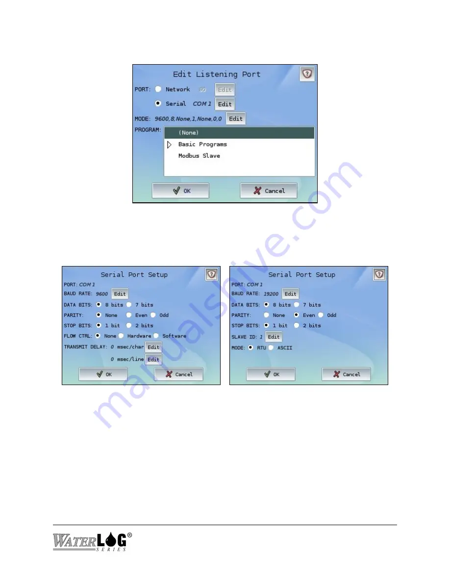
options to configure the port exactly as needed.

Mode:

 Displays the current serial port setup.  To modify the setup, press the Edit button.


The following standard serial port options can be customized: baud rate, data bits, parity, stop
bits, etc.  Most programs allow flow control as well as transmit delays to be configured.  If a
Modbus Slave program is selected, the Modbus Slave ID as well as mode (RTU or ASCII) will
become available as part of the Serial Port Setup.

System 5000

System Setup - Communications 11-5

TM

Summary of Contents for WaterLog Series

Page 1: ...Model System 5000TM Owner s Manual Revision 1 4 2...

Page 2: ......

Page 3: ...Ports 2 2 Ethernet Port 2 2 RS 232 Ports 2 3 SDI 12 Ports 2 4 Switched 12 Volt Excitation 2 4 Power Connection 2 4 AC Input 2 4 Digital I O 2 4 Analog Input Section 2 5 4 to 20 Milliamp 4 20mA Output...

Page 4: ...6 Digital In 5 7 Level 5 7 Frequency 5 8 Event Counter 5 8 Quad Counter 5 9 Internal Temperature 5 10 Modbus Master Input 5 10 Modbus Slave Input 5 11 SDI 12 Sensor 5 11 User Defined Task 5 13 Chapter...

Page 5: ...hapter 8 Modbus 8 1 Modbus Overview 8 1 Supported Function Codes 8 1 Configuring Modbus 8 2 Determining Modbus Master or Modbus Slave 8 2 Creating a New Port 8 3 Using an Existing Port 8 3 Port Settin...

Page 6: ...Setup Inputs Outputs 12 1 Inputs Outputs Screen 12 1 Basic Program Management 12 2 Log File Configuration 12 3 Tasks Overview 12 4 View Status Screen 12 5 Chapter 13 Connecting with a PC 13 1 Direct P...

Page 7: ...Appendix A System 5000 Specifications A 1 Appendix B Pressure Sensor Option Module Specifications B 1 Appendix C Analog Digital Option Module Specifications C 1...

Page 8: ......

Page 9: ...ODUCT extended to you by DESIGN ANALYSIS and to protect the confidential and proprietary information of DESIGN ANALYSIS USER agrees as follows a USER agrees that they will not remove from the exterior...

Page 10: ...THE EXPRESS WARRANTIES ABOVE DESIGN ANALYSIS SPECIFICALLY DISCLAIMS ALL OTHER WARRANTIES INCLUDING WITHOUT LIMITATION ALL IMPLIED WARRANTIES OF MERCHANTABILITY AND FITNESS FOR A PARTICULAR PURPOSE iii...

Page 11: ...lug in modules allow the data logger to be configured for a wide variety of monitoring data logging and SCADA applications Current option modules include Precision pressure sensor module Analog Digita...

Page 12: ...mperature compensated real time clock with lithium backup battery Plug in terminal strip connectors Fiberglass enclosure with lexan window Operates over a wide temperature range 40EF to 140EF 40EC to...

Page 13: ...s to be added for simple expandability and are field upgradable Some option modules may take up more than one slot when installed The following plug in option modules are currently available Precision...

Page 14: ...Getting Started Guide 6FT USB 2 0 Cable Data Cable Optional Items Expansion Module s Cables Sensors SD Memory Card USB Thumb Drive Additional Support and Documentation The web page at http www waterl...

Page 15: ...ations The Power LED blinks every five seconds while power is applied to the unit The Active LED illuminates when the unit is taking measurements collecting data or performing other background tasks W...

Page 16: ...al memory using the Data File Manager The USB B TM connector is provided to allow a direct connection from the System 5000 to a computer When TM connected in this manner the System 5000 can be seen as...

Page 17: ...gender changer if connected to a PC DTE type device The NULL modem cable crosses the communication lines allowing two similar devices to communicate The pin out for the RS 232 ports is shown below SE...

Page 18: ...TM front panel will blink every five seconds when sufficient power is connected AC Input The AC Input is provided to connect sensors that have a low level AC output like wind speed sensors A wind spe...

Page 19: ...nalog grounds only for sensors connected to the analog section The current flowing through an analog sensor is relatively small and normally very stable If a digital sensor has its ground connection t...

Page 20: ...ay want to connect a temperature probe to the System 5000TM and convert the temperature value into a 4 20mA output A temperature probe on Analog Channel 1 that produces a 0 to 5 volt output representi...

Page 21: ...ly accurate digital pressure transducer specifically designed for water level monitoring The module directly measures dry gas pressure over a broad temperature range and is typically to be used with t...

Page 22: ...l connectivity and communications The module includes two digital grounds an AC In four digital I O ports a 5V reference a 4 20 milliamp output two analog grounds and eight analog channels that can be...

Page 23: ...late Insert the option module into the opening verifying the card is secured within the guide rails inside the System 5000 TM Press the card firmly into the System 5000 and replace the screws Reconnec...

Page 24: ...2 10 Hardware Overview System 5000TM...

Page 25: ...the System 5000 or an attached USB thumb drive or SD TM memory card System configuration saving loading Firmware updating and other options are also performed here The System Setup section is used to...

Page 26: ...saves any changes to the current screen When changes are detected the OK label turns blue The Cancel button discards any changes made to that screen Screens with Exit buttons save changes automaticall...

Page 27: ...asks on the System 5000 will probably be set up and used based on a common scan TM rate If a scan rate of 15 minutes was chosen and all Tasks were setup as such every 15 minutes the desired Inputs wou...

Page 28: ...with the options provided here Some options may be grayed out if a Task is not selected Only existing selected Tasks may be modified or deleted Task Priority The priority of Tasks can be changed thro...

Page 29: ...tion pertinent to the new or existing Task Naming a Task Task Label Defines the unique name used for this Task throughout the system To change the Task name press the Edit Label button on the Edit Tas...

Page 30: ...card is installed additional Inputs may be available and are designated by their slot within the system The above screen depicts an Analog Digital expansion module installed in Slot 1 Select the desi...

Page 31: ...s can be edited by pressing the Edit button next to the current Scan Rate Advanced Scanning Options such as Scan Offsets Start Stop Times and Scan Intervals can be attributed to individual Tasks by pr...

Page 32: ...an Offset of negative 30 seconds 00 00 30 in the above scenario would cause the Batt Task to take measurements at 00 14 30 00 29 30 00 44 30 etc Scan Offsets allow a common Scan Rate to persist despi...

Page 33: ...edule will be repeated If any errors are found within the Task Schedule an error message will be displayed when the OK button is pressed All errors must be corrected before a Task Schedule can be used...

Page 34: ...stom function can be assigned to each Task A default Slope of 1 0 and Offset of 0 0 will cause the Task value to remain unchanged To change which option to use select the radio button next to the desi...

Page 35: ...to when the measurement was retrieved a history of values will be displayed in the action Log window Auto Set Value An Offset can be automatically calculated at any time for the given sensor By pressi...

Page 36: ...en is accessed by first pressing the radio button next to the Custom Function option then pressing the Edit button next to the existing Custom Function on the Math Data Options page The Custom Functio...

Page 37: ...true 0 if false x y Is x greater than y 1 if true 0 if false x y Is x greater than or equal to y 1 if true 0 if false x y Is x less than y 1 if true 0 if false x y Is x less than or equal to y 1 if tr...

Page 38: ...ees ATAN 0 5 26 565051 sinr x Sine of x based on radians SINR 1 0 841471 cosr x Cosine x based on radians COSR 1 0 540302 tanr x Tangent x based on radians TANR 1 1 557408 asinr x Arc sine x based on...

Page 39: ...see the app note for its full details h377c AnalogX Convert the voltage on analog channel X specified in Task AnalogX from the H 377 thermistor probe to temperature in degrees Celsius The following is...

Page 40: ...rent Task to be used The current Task value will appear as RawValue in the list Note that some values may not appear in the list and can thus cause an ERR or erroneous value to appear when pressing th...

Page 41: ...he system The above screen depicts an Analog Digital expansion module installed in Slot 1 Select the desired Output and press the OK button to open the Properties for that Output De selecting the chec...

Page 42: ...modify the Timed Rate or other Advanced Scanning Options press the Edit button next to the listed rate Rates are in a 24 hour format of HH MM SS Timed Rates can be useful for example with a Log To Fi...

Page 43: ...ut from myTask will only prevent myTask from being recorded to that log file on future scans All other Tasks recording to that log file will continue to log as expected Running a Task On occasion a Ta...

Page 44: ...Deleting a Task removes the Input from retrieving further measurements and any Outputs that utilized this Task Any Custom Functions Conditional statements or Basic Programs that directly referred to t...

Page 45: ...HH MM SS Digital Input modes of Level and Event Counter have another Type available called Edge Triggered This Event driven Type causes the System 5000 to awaken when the chosen TM Digital Edge rises...

Page 46: ...for wind speed sensors but can be used with any sensor that produces a low level AC frequency output The AC signal is normally in the range of 0 15 volts peak to peak centered at 0 00 volts Though th...

Page 47: ...og input Channels have a 0 0 to 5 0 Volt input range As the internal A D has 24 bits of resolution low level output voltage 0 0 to 500 mV is inherently supported and accurately measured on all channel...

Page 48: ...n process for that particular analog channel will take longer Generally only a few samples are necessary for an extremely accurate reading Est Time sec The Estimated Time will be updated as the Number...

Page 49: ...ged using the View and Debug buttons It is a good idea to test Debug each Basic program before enabling scanning to verify the program will run as expected Any special variables known as Symbols withi...

Page 50: ...enerally a battery is connected to and provides power to the System 5000 As a good battery TM is key to a healthy data logging system having access to this value can be very beneficial No extra proper...

Page 51: ...er Modes allow the Edge Triggered Event driven Type to be used Level The default mode for a Digital Input is Level This Digital Value gives the current state of the digital I O pin As an Input the val...

Page 52: ...with rain gauge type applications However the counter can also be used with any sensor that acts as a switch closure or produces a 0 to 5 volt pulse The Slope located under Math Data Options will pro...

Page 53: ...r Options Allows the counter to be set to a certain value or reset to zero Quad Counter Two Digital Input pins can be used together for applications using a quadrature input Ports 1 and 2 or 3 and 4 c...

Page 54: ...Format Defines the scale on which the temperature measurement is based Modbus Master Input Modbus Master can be utilized as both an Input and or an Output Modbus Master Input enables the System 5000 t...

Page 55: ...twork TM The Input reads from the designated internal register and uses the register s value as the Task value retrieving the latest value on each scan The designated register should be written to fro...

Page 56: ...can be any single digit number or letter Sensor addresses are case sensitive thus sensor H is different from sensor h Most sensors typically use a number for their address Finding unknown sensor addre...

Page 57: ...used for example as a simple measurement counter by assigning a Custom Function of RawValue 1 telling the Task value to increment every time it is run The User Defined Task could also be used as a ge...

Page 58: ...5 14 Inputs System 5000TM...

Page 59: ...Scan Rate or on a different time interval values may not be available for the Output to use To modify the Timed Rate press the Edit button next to the listed rate Rates are in a 24 hour format of HH...

Page 60: ...n either be done through the Add Output selection screen or through the System Setup Inputs Outputs Log File Configuration screen The following sections will cover only setup through the Add Output sc...

Page 61: ...e existing log file configuration No further steps are necessary for the Task value to begin logging once Scanning is Enabled from the Main Menu Log To File Properties After selecting the Log To File...

Page 62: ...nged a simple preview can be viewed Tasks can be added or removed and more advanced logging options can be altered from here File Defines the current log file name The name can be changed by pressing...

Page 63: ...sk Inputs are run first followed by all Task Outputs both according to Task Priority Move the selected Task up one level Move the selected Task down one level The Edit Task button allows additional pr...

Page 64: ...of all values in the given range e g MM DD YYYY HH MM SS timeofmax Returns the date and timestamp of the maximum value of all values in the given range e g MM DD YYYY HH MM SS intervalmin Prints the...

Page 65: ...ormally remain empty to be filled with the given value or string Delimiter Defines the delimiter used between values within the log file The default comma delimiter allows a common comma separated for...

Page 66: ...ation at the same time The System 5000 will check if data is to be sent to the GOES Radio data buffer after each scan interval If TM data is in the GOES Radio timed data buffer it will be transmitted...

Page 67: ...ar buttons and labels Transmitting this Task By default the Task will not be added to the GOES transmission until explicitly told to do so through the GOES Properties screens The simplest way to do th...

Page 68: ...0 and Design Analysis H 2221 radios are supported To select or change the Radio Type press the Edit button next to the current label Port Defines the port on which the current GOES Radio is connected...

Page 69: ...ddress This is the 8 character DCP Data Collection Platform address or ID assigned by NESDIS This is automatically transmitted with the data to the GOES satellite The address must be in capital letter...

Page 70: ...5000 Time Displays the current time on the System 5000 TM Synchronize Though set to None by default the System 5000 can be set to synchronize with TM the GOES time due to the accuracy of the GPS syst...

Page 71: ...imed transmissions based on the Transmit Rate This is also the time of the first transmission of the day relative to midnight This offset time is also assigned by NOAA and must be less than the Transm...

Page 72: ...e other hand Binary data is transmitted quicker but the file will need to be decoded before it can be read If more data needs to be transmitted within the specified window the Binary format may have t...

Page 73: ...efines how the data will be presented Regarding the Default layout the data will be sent based on each transmitted line representing a single scan or each transmitted line representing a single channe...

Page 74: ...ould cause the next transmission to contain only data collected since the last transmission The default value is 1 indicating that one set of extra or redundant data will be sent along with the new da...

Page 75: ...y of options with only a few specifics detailed below Common to both are the following options Tx Buffer Displays the approximate used and total number of bytes available for the transmission The tota...

Page 76: ...g occurs every 15 minutes the Transmit Rate is set to every hour and the Self Timed Transmit Time is set to 00 22 15 the radio buffer would be visible after the scanning at the 15 minute mark e g 00 1...

Page 77: ...that many characters Right of the Decimal Sets the number of digits to display to the right of the decimal Selected Format Displays the format based on the selections of the above two options SHEF Cod...

Page 78: ...nts to 1 would yield the result of x y max Returns the maximum value of all values in the given range min Returns the minimum value of all values in the given range sum Returns the summation of all va...

Page 79: ...ious entries and may re schedule the random transmission A smaller window than the Scan Rate will allow all Random transmissions to be successfully sent and not overwritten or replaced Transmit Condit...

Page 80: ...for the function to be true which would cause a random transmission The Transmit Condition is of the same format as Custom Functions and Conditional statements See Chapter 4 regarding Custom Functions...

Page 81: ...of how the battery is holding up Mainly look at the difference between the voltage during the last transmission and one of the other readings to see if there is a large difference The current tempera...

Page 82: ...d Random Tx To test sending a random message this option will send the message This is a test message over the set Random Channel at the baud rate specified in the Random Options Specific to the H 222...

Page 83: ...satellite used to rebroadcast GOES data DRGS Direct Readout Ground Station A receiver capable of receiving data directly from the GOES satellite DPS Data Processing System GMT Greenwich Mean Time All...

Page 84: ...is table describes the Radio manufacture and model number Preamble This is a carrier signal sent to the satellite before any data is sent Only 100 baud transmissions can send a Long Preamble Preamble...

Page 85: ...ll be stripped off by the time the data is sent to the decoding software Bit 6 is always set to 1 forcing the data byte to always be a printable character in the ASCII table Valid characters along wit...

Page 86: ...8388 608 0 0032 0 2048 13 1072 838 8608 31 2047 131071 8388607 3 1 204 7 13107 1 838860 7 0 31 20 47 1310 71 83886 07 0 031 2 047 131 071 8388 607 0 0031 0 2047 13 1071 838 8607 1 1 1 1 0 1 0 1 0 1 0...

Page 87: ...x 204800 1216 56 206072 r in the left position 204800 S in the middle position 1216 x in the right position 56 Total 206072 This is greater than 131071 so subtract it from 131072 206072 131072 75000 T...

Page 88: ...12 l 11534336 180224 2816 44 M 3407872 53248 832 13 m 11796480 184320 2880 45 N 3670016 57344 896 14 n 12058624 188416 2944 46 O 3932160 61440 960 15 o 12320768 192512 3008 47 P 4194304 65536 1024 16...

Page 89: ...256 286 317 347 14 14 45 73 104 134 165 195 226 257 287 318 348 15 15 46 74 105 135 166 196 227 258 288 319 349 16 16 47 75 106 136 167 197 228 259 289 320 350 17 17 48 76 107 137 168 198 229 260 290...

Page 90: ...348 14 14 45 74 105 135 166 196 227 258 288 319 349 15 15 46 75 106 136 167 197 228 259 289 320 350 16 16 47 76 107 137 168 198 229 260 290 321 351 17 17 48 77 108 138 169 199 230 261 291 322 352 18...

Page 91: ...be within the assigned time window In this transmission it was at 18 hours 49 minutes and 03 seconds 163708DE08078184903G51 1NN021EUB00023BCT DZ DY Dc Db Dm Dxj The next byte indicates if the transmis...

Page 92: ...ata bytes are in the transmission In this case 00023 data bytes were expected 163708DE08078184903G51 1NN021EUB00023BCT DZ DY Dc Db Dm Dxj This is the end of the header information added by the GOES sy...

Page 93: ...ll be used as the program name and title of the Properties screen Program The Basic Program can be viewed or debugged using the View and Debug buttons It is a good idea to test Debug each Basic progra...

Page 94: ...the Task s Input For example if a temperature probe was being measured and had a range of 50 to 50 degrees the Max level would be set to 50 and the Min level set to 50 With this setup a temperature of...

Page 95: ...age levels to verify they are ok If the current meter reads zero milliamps the wires could be connected backwards or there is no power source for the loop Remember that this output controls the curren...

Page 96: ...allowed evaluating any positive number as true and zero or less as false Be aware that though the Digital Output may be set to a 1 or a 0 the connected equipment may prevent the Output from going to t...

Page 97: ...asures less than or equal to 10 0 at which time it will be set to 0 Low Pulse The selected Port will briefly turn On 1 for the given number of milliseconds if the Condition evaluates to true For examp...

Page 98: ...ut writes to the designated external Modbus Slave register according to the specified register setup and selected Port More information regarding Modbus can be found in Chapter 8 of this manual Modbus...

Page 99: ...s By default the Switched 12V excitation is set to be always on To save power or have finer control over the port the Task Selected option can be chosen to determine the exact times the port will be a...

Page 100: ...d on when the Task Output is run in this manner On For Scan The excitation port will turn on at the beginning of each scan and delay the entire scanning process for a time specified by setting the War...

Page 101: ...tructs such as goto gosub and line numbers Both number and string variables including single and multi dimensional arrays Built in string and variable processing functions Easy access to COM Serial Po...

Page 102: ...an also be modified Installing a Basic 5000 Program Basic 5000 programs can be easily installed by pressing the Add New Program function button on the Basic Program Management screen Simply select a d...

Page 103: ...put select menus If no group is specified the program will be listed under the Basic Programs group If an alternative group is specified the Program will be listed under the given group name A special...

Page 104: ...ll also appear in this window This window can also fill the entire screen by pressing the Toggle View button To Start debugging a Basic Program press the Start Program button in the bottom left corner...

Page 105: ...s Master requests return the most recent measured value of the assigned Task Modbus supports communication over the RS 232 and Ethernet ports supporting the RTU ASCII and TCP Modbus protocols Modbus M...

Page 106: ...us Master I O should be used when the System 5000 is expected to initiate TM communication with other Modbus Slave devices on the network Modbus Master Input indicates a value will be read from a Modb...

Page 107: ...assign a new port to be used with Modbus The port and settings can be further configured on the Modbus Properties screen after the OK button is pressed Using an Existing Port Adding additional Tasks t...

Page 108: ...port press the Settings button on the Modbus Master Properties screen or the Edit button on the Edit Listening Port screen Modbus Master setups can also specify a connection timeout in milliseconds as...

Page 109: ...l be read each scan If the Task is an Output the value of the Task will be written to the register s each scan Register addresses begin numbering at 1 Some Modbus Masters and Slaves however retrieve r...

Page 110: ...e two registers may be swapped by selecting the Inverse option Short and Long store only whole integer values non decimal and can be unsigned allowing only positive values to enable a greater range Fl...

Page 111: ...extension beginning at 001 For example the first archive of a log file named SiteID csv would be SiteID csv 001 Archiving rules for individual log files apply as specified under the Advanced Logging O...

Page 112: ...utton provides a quick and easy method for allowing new data to be stored in a fresh log file while maintaining the old data in older files For example when returning to a site to retrieve the collect...

Page 113: ...press the Save Config function button All system settings Tasks and any installed Basic Programs will be saved as part of the configuration To load a new configuration onto the System 5000 select a p...

Page 114: ...Data File Manager After a firmware upgrade file has been downloaded most likely from the waterlog com web site and stored on an SD card or USB thumb drive select the firmware file and press the Firmw...

Page 115: ...include Date Time Diagnostics Menu Help Documentation Password Protection System Information and System Settings Some sections may be familiar as portions of these screens are fully accessible throug...

Page 116: ...OES transmitter is attached the date and time can be synchronized with an optional local offset via the GOES GPS through the GOES Time Setup screen accessible through the GOES Configuration Time Shows...

Page 117: ...y select the desired option and press the Open button Note that as all Diagnostic screens contain onscreen instructions the Help Documentation button will be disabled It is also recommended that Scann...

Page 118: ...tal The Digital Self Test verifies that each digital port can be properly set as an Input or Output and the expected reading can be measured Disconnect all digital sensors before performing this test...

Page 119: ...operations Serial Ports Testing Proper communications through the serial ports can be evaluated via the Serial Port Testing screen To test a serial port first attach a loopback connector then press t...

Page 120: ...System Setup To see the documentation regarding a certain topic select the desired Help Topic and press the View button As many screens contain similar properties e g all Task Inputs have a Scan Rate...

Page 121: ...led radio button To disable password protection that has been enabled select the Disabled radio button When enabled a Login screen will appear upon boot up and when the display turns off requesting th...

Page 122: ...urrent Tasks and values as well as new measurements to be seen by any who access the 5000 while modifications to the system configuration are not available Access to the View Status screen can be disa...

Page 123: ...shooting For example the last reboots of the system can be helpful in determining if proper power is being supplied or if other potential problems may be occurring within the system The Save Info func...

Page 124: ...eserving the values across power failures and reboots Switched 12V Defines the mode of the SW D 12V port on the front panel of the System 5000 The Switched 12 volt excitation is provided to power sens...

Page 125: ...his value The default setting is 15 minutes 00 15 00 Default Precision Defines the precision number of digits to the right of the decimal assigned to new Tasks Existing Tasks will not be affected by c...

Page 126: ...n off to save on power consumption System Timeout Defines the amount of time before the system will go to sleep after shutting off the touchscreen display If None is selected the system will never go...

Page 127: ...l GOES Transmissions will be scheduled and run regardless of the measured battery voltage level If the second option is selected GOES Transmissions will only be scheduled and run when the voltage leve...

Page 128: ...10 14 System Setup General Setup System 5000TM...

Page 129: ...ies include GOES Configuration Network Listening Ports Network Setup Remote Assistance and SDI 12 Transparent Mode Some sections may be familiar as portions of these screens are fully accessible throu...

Page 130: ...GOES Configuration The GOES Configuration screen allows the general status and operations of an attached GOES Radio to be seen and configured The GOES Radio must be properly set up and operational bef...

Page 131: ...l listening ports much be unique Port Options Listening ports can be added edited and removed with the options provided here Some options may be grayed out if a Task is not selected Only existing sele...

Page 132: ...e menu system seen through the touchscreen and thus enable remote communication configuration and data retrieval from the system via a network connection As the VNC Server also supports file transfers...

Page 133: ...tup To modify the setup press the Edit button The following standard serial port options can be customized baud rate data bits parity stop bits etc Most programs allow flow control as well as transmit...

Page 134: ...ver should TM not be used when connected to a network with another DHCP server IP Type Specifies how the IP address will be set on the system The IP Address is a unique identification on a given netwo...

Page 135: ...issues that may arise System 5000 IP Defines the current IP address associated with the System 5000 An IP TM address is necessary for the Remote Assistance option to operate correctly If an IP addres...

Page 136: ...new address For example if the existing Sensor Address was 0 and needed to be changed to 1 by pressing the Edit button next to this label entering 1 and pressing OK would issue an address change comma...

Page 137: ...Verify Command Start Measurement Sends the sensor address followed by M which is the standard SDI 12 measure command The response to this command is the time required to make the measurement and the...

Page 138: ...tended Commands are sent exactly as entered followed by the terminator if not specified All SDI 12 communication can be seen in the above window Refer to the sensor manufacturer s documentation for pr...

Page 139: ...es include TM Basic Program Management Log File Configuration Tasks Overview and View Status Screen Some sections may be familiar as portions of these screens are fully accessible through various menu...

Page 140: ...e displayed in the left box with their associated Type Program Name and Filename The Type can have up to three letters displayed I O and N relating to where the program will be available Input Output...

Page 141: ...ndividual configurations via the Disable Enable Log function button Config Options New configurations can be created and selected configurations can be edited or removed through the New Edit and Remov...

Page 142: ...hown To view the Outputs associated with each Task simply select the row of a Task and it will expand To quickly Expand or Collapse all Tasks press the Expand All function button This screen can be he...

Page 143: ...essing and holding the View Status button for more than three TM seconds will initiate the action specified by the function button If no Tasks are selected and the Measure All function button is shown...

Page 144: ...12 6 System Setup Inputs Outputs System 5000TM...

Page 145: ...y supported enabling the latest data files to be retrieved TM or firmware upgrades to be uploaded Microsoft Windows XP is used in the examples below Set up on all other Microsoft Windows products are...

Page 146: ...tely configure To test whether the IP address assignment was successful simply open a web browser and enter the IP address displayed on the Direct PC Setup page into the address bar and press Enter Up...

Page 147: ...the chapter USB Virtual Serial Port Driver Installation Two versions of the USB driver are available gserial inf and gserial64 inf These files can be retrieved by pressing the Drivers button on the D...

Page 148: ...ress the Next button Check the Include this location in the search and press the Browse button Select the folder or location of the driver files that were saved previously and press the OK button Then...

Page 149: ...be installed a warning message may appear Press the Continue Anyway to allow the driver to be installed properly Once the driver has been installed press the Finish button to exit the driver installat...

Page 150: ...n the Desktop of the PC to make future connections quick and simple Before proceeding verify the System 5000 has been set up and configured as noted above and TM the PC is connected to the System 5000...

Page 151: ...modem I will select it from a list option and press Next Select Standard Modem Types from the Manufacturer column Select Standard 33600 bps Modem from the Models column and press Next System 5000 Con...

Page 152: ...lect the COM port the System 5000 is connected to TM USB virtual serial ports are typically the highest number COM port Press Next Once the modem installation has completed select the Finish button 13...

Page 153: ...attached to Highlight the new modem and press the Properties button Select the Modem tab and verify the Maximum Port Speed is set to 115200 If it is not select 115200 from the drop down list Press OK...

Page 154: ...o connect to the System 5000 TM To set up Dial Up Networking select the Start button Control Panel Network Connections in Classic View Select Create a new connection under the Network Tasks menu on th...

Page 155: ...he computer a prompt will appear asking which Modem and COM port should be used If only one port is set up as a Modem this screen will not appear Select the modem Standard 33600 bps and press the Next...

Page 156: ...ion to my desktop and press the Finish button After completing the Dial Up Networking setup some quick changes to the connection need to be configured Press the Properties button on the pop up window...

Page 157: ...pt for name and password certificate etc as well as the Prompt for phone number Dialing options Select the Networking tab highlight the Internet Protocol TCP IP option and press the Properties button...

Page 158: ...nges The connection may automatically try to connect at this point If it does not simply double click on the Desktop icon to initiate a new connection to the System 5000 If connecting via the TM USB D...

Page 159: ...Serial ports will report 115 2 Kbps as their speed USB connections may report 9 6 Kbps though the speed is actually 115 2 Kbps as well Once connected simply open a web browser and type in the address...

Page 160: ...System 5000 and then to a USB port on a computer The TM following screen will be displayed noting that scanning will be disabled while the System 5000 is operating as an external USB device TM Pressin...

Page 161: ...he screen can be pressed to end the connection Using a Web Browser Once the System 5000 has been properly configured and is connected by either USB Serial or TM Ethernet the touch screen interface men...

Page 162: ...the computer may need to be updated Please visit www java com to download and install the latest Java client The System 5000 menu interface should appear once the Java process has finished loading TM...

Page 163: ...de windows System 5000 files are shown TM in the right side window Selected files may be copied to and from the System 5000 using the TM Send and Receive buttons as well as removed using the Delete Fi...

Page 164: ...ecified using port 180 to connect An example setup of the UltraVNC Viewer on a PC is shown below Alternative ports can be used for connecting by creating additional Listening Ports and selecting the V...

Page 165: ...ile applying power to the System 5000 Continue to hold the View Status button until the first TM System 5000 splash screen appears Within a few seconds a simple touchscreen calibration TM menu will ap...

Page 166: ...ions you have found to past problems at 435 753 2212 Our experience with pressure transducers has taught us a lot about the problems associated with field installed equipment The following list of pro...

Page 167: ...r for correct wiring 4 Make sure all sensors have a unique address GOES Transmissions GOES not transmitting 1 Check power to the GOES Radio do so under a load e g a transmission 2 See if the GOES time...

Page 168: ...14 4 Maintenance and Troubleshooting System 5000TM...

Page 169: ...x Negative going 1 8V min 1 1V max Output Voltage Low 0 5V max 24mA High 3 8V min 24mA Event Frequency Quadrataure Input Type 4 inputs switch closure or voltage pulse Programmable rising or falling ed...

Page 170: ...A 2 System 5000 Specifications System 5000TM...

Page 171: ...re Hysteresis Less than 0 01 of FSO Long term Stability Accuracy drift is less than 0 05 of FSO per year Response Times Pressure only 10 second measurement sequence Pressure Temp 10 second measurement...

Page 172: ...B 2 Pressure Sensor Option Module Specifications System 5000TM...

Page 173: ...utput Internal 47K pullup resistor to 5V Voltage 0 5V input output Input Type Schmitt hysteresis 0 7V min 1 1V max Input Voltage Positive going 2 6V min 3 3V max Negative going 1 8V min 1 1V max Outpu...

Page 174: ...C 2 Analog Digital Option Module Specifications System 5000TM...

Reviews: