


IM 12B07D02-01E
6-4 Calibration
pH
NO
YES
pH
NO
YES
YES
NO
NO
YES
pH
YES
pH
pH
NO
YES
ENT
pH
pH
pH
pH
NO
YES
Put sensors in buffer
solution. Press
YES
.
Set the value
using the
>
, ,
ENT
key.
Select the flashing digit with the
>
key.
Increase its value by pressing the key.
When the correct value is displayed, press
ENT
to enter the change.
>
>
12B6C3-32
pH
NO
YES
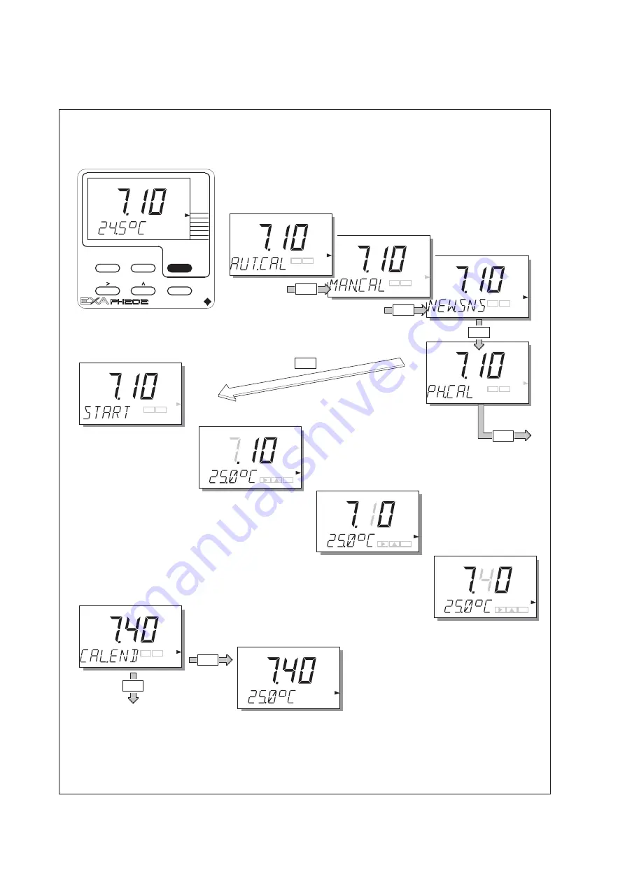
Manual Calibration.
(2nd parameter calibration)
Press the
MODE
key. The legend AUT.CAL appears,
and the YES/NO key prompt flags flash. Press
NO
.
The display MAN.CAL appears.
Press
YES
to start calibration.
Press
YES
or
NO
at NEW.SNS prompt.
YES
NO
For 2 point (As Pot and Slope)
Adjustment select second buffer
solution and adjust as for pH7 buffer.
NO
ENT
ENT
YES
WAIT is displayed
briefly then EXA returns
to measuring mode.
pH
ENT
MAN.CAL
DISPLAY
HOLD
NO
MODE
YES
YOKOGAWA
MODE
TEMP
AUT.CAL
MEASURE
(Note: Press
NO
to start
calibration of zero point when
enabled in Service Mode).
6-5-3. Manual calibration (2nd parameter calibration)
Summary of Contents for PH202G (S)
Page 5: ...IM 12B07D02 01E ...
Page 9: ...IM 12B07D02 01E LT LV PL EST SLO H BG RO M CZ SK ...
Page 13: ...IM 12B07D02 01E 1 4 Introduction ...
Page 86: ...IM 12B07D02 01E Spare parts 9 1 9 SPARE PARTS See Customer Maintenance Parts List ...
Page 96: ...IM 12B07D02 01E 10 10 Appendix ...
Page 116: ...IM 12B07D02 01E 12 4 Appendix ...
Page 120: ...IM 12B07D02 01E 12 8 Appendix ...
Page 124: ...IM 12B07D02 01E 12 12 Appendix ...
Page 128: ...IM 12B07D02 01E 12 16 Appendix ...


