YG48Q-5A Maintenance ManualClutch and Right crankcase cover
77
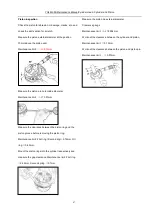
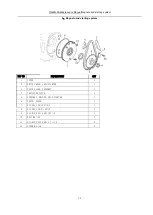
Disassemble and assemble of clutch
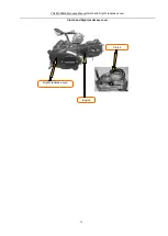
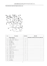
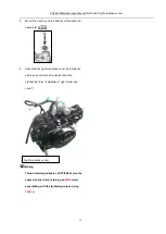
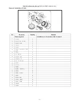
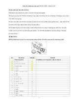
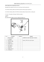
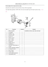
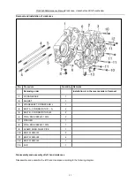
Disassemble and assemble the clutch according to the following diagram.
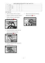
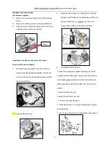
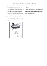
While removing the clutch lift plate, alternatively loosen the 6connecting bolts to avoid damage of cracking due to uneven
force of the clutch spring.
While mounting the clutch lift plate, alternatively loosen the 6 connecting bolts to the specified torque. Assemble with the
protruding side of the butterfly washer facing the plain washer
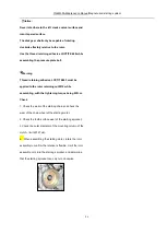
While assembling, the clutch disc must be coated with lubricating oil; in case of replacing new clutch disc, it must be
soaked in oil for over 24 hours before being assembled. Do not further disassemble the clutch housing, otherwise
damage will occur.
Explanation:
While unscrewing bolt, do it in a crossing way twice or thrice. Do in the same way for screwing up bolt.
No
Procedure
Quantity
Remarks
Removing order
Installation is in the reverse order of removal
1
CLUTCH
1
2
DRIVE GEAR, PRIMAR
1
3
FIXING PLATE
1
4
CIRCLIP
1
5
COLLAR
1
a
SPRING, CAM PLATE, SIDE
COVER
1
b
SPRING
1
c
PIN KNOCK
1
d
BEARING 6000
1
e
SCREW M5×12
4
f
CAP, CLUTCH END
1
g
GASKET
1
h
NUT M14
1
i
WASHER
1
j
WASHER, STOPPING
1
k
SPRING
4
l
COVER, CLUTCH
1
Summary of Contents for YG48Q-5A
Page 38: ...YG48Q 5AMaintenance ManualFuel system 41 4 Fuel system...
Page 92: ...YG48Q 5AMaintenance ManualFrame and exhaust system 105 10 Frame and exhaust system...
Page 123: ...YG48Q 5A Maintenance ManualIllumination signal system 136 Circuit schematic drawing...
Page 126: ...YG48Q 5A Maintenance ManualIllumination signal system 139...
Page 133: ...YG48Q 5A Maintenance ManualEngine management system 146 Major parts and components...
Page 134: ...YG48Q 5A Maintenance ManualEngine management system 147...
Page 144: ...YG48Q 5A Maintenance ManualElectrical System Diagram 157 19 Electrical System Diagram...

