YG48Q-5AMaintenance ManualCrankcase, crankshaft and Shift mechanism
95
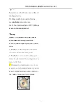
Generally, do not remove the bearing; if it is removed, coat engine oil on surfaces of spare parts while pressing it in; mount
it with SST and confirm the press-in depth of the bearing. Assemble the driven shaft bearing with the with oil seal facing
inwards.
Disassembling the needle bearing may damage it; in case it is damaged, always change a new one.
Replace washer with new ones after being removed.
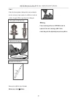
Apply the thread retaining adhesive LOCTITE 648 while assembling the stud bolt.
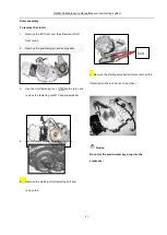
Notice:
Do not the sealing surface, and assemble the driven shaft bearing with the side with oil seal facing inwards.
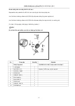
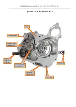
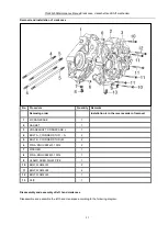
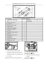
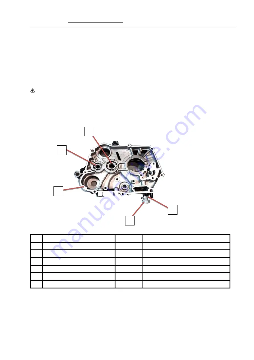
No.
Procedure
Quantity
Remarks
Removing order
Installation is in the reverse order of removal
1
Right hand crankcase
1
2
Crankshaft bearing 6201
1
3
Crankshaft bearing 6203
1
4
BOLT,DRAIN PLUG
1
5
WASHER
φ12
1
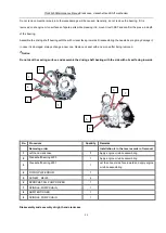
1
2
3
4
5
Summary of Contents for YG48Q-5A
Page 38: ...YG48Q 5AMaintenance ManualFuel system 41 4 Fuel system...
Page 92: ...YG48Q 5AMaintenance ManualFrame and exhaust system 105 10 Frame and exhaust system...
Page 123: ...YG48Q 5A Maintenance ManualIllumination signal system 136 Circuit schematic drawing...
Page 126: ...YG48Q 5A Maintenance ManualIllumination signal system 139...
Page 133: ...YG48Q 5A Maintenance ManualEngine management system 146 Major parts and components...
Page 134: ...YG48Q 5A Maintenance ManualEngine management system 147...
Page 144: ...YG48Q 5A Maintenance ManualElectrical System Diagram 157 19 Electrical System Diagram...

