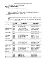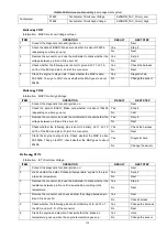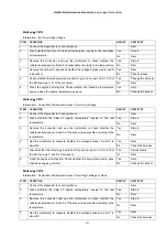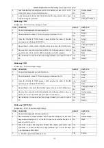
YG48Q-5A Maintenance ManualEngine management system
145
18
、
Engine management system
System Overview
Components of system and Operating principle
The Engine Management System(EMS) comprises electronic control unit(ECU), throttle body, Idle speed control valve,
fuel pump, fuel injector, ignition coil, O2 sensor, throttle position sensor, T-MAP sensor, cylinder head temperature sensor
and so on. Based on the air flow and engine speed, the fuel injector and ignition coil are controlled by ECU to get the
optimal combustible mixture of fuel and air and Ignition timing which meet all engine operating conditions. The EMS use
sensors to collect parameters such as air flow, temperature of inlet air, cylinder head temperature, atmospheric pressure
and the operation state of engine (rpm, load, acceleration and deceleration). All parameters are transferred to the ECU
with electronic signal. The ECU output controlling signals after input signal are handled. Through the engine and actuators
on the vehicle (ignition coil, fuel injector, Idle speed control valve and so on), the fuel and fire are exactly controlled and
corrected with closed loop. For production conformity, corrected fuelling in order to match up to the difference of vehicles
due to the inconformity of components.
System composition:
1.
Sensor:
• Intake air pressure sensor (load information) intake air temperature and pressure sensors
• Throttle position sensor (load information, load range information, acceleration/deceleration information)
• Engine speed sensor (speed information, crankshaft position)
• Intake air temperature sensor (air density information)
• Oxygen sensor (information of the excess air coefficient is more than 1 or less than 1)
2.
Actuator:
• Fuel pump relay,
• Fuel pump
• Fuel injector (fuel supply)
• Ignition coil
• High-tension cord
• Spark plug (ignition)
• Throttle, Idle speed control valve (air intake)
3. Electronic control unit
• ECU
System Overview
Tools
Major parts and components
Maintenance depending on the malfcode
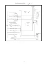
Circuit schematic drawing
Maintenance depending on the performance
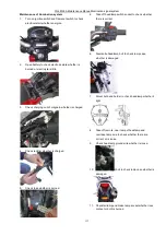
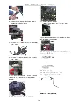
Maintenance of Engine management system
Summary of Contents for YG48Q-5A
Page 38: ...YG48Q 5AMaintenance ManualFuel system 41 4 Fuel system...
Page 92: ...YG48Q 5AMaintenance ManualFrame and exhaust system 105 10 Frame and exhaust system...
Page 123: ...YG48Q 5A Maintenance ManualIllumination signal system 136 Circuit schematic drawing...
Page 126: ...YG48Q 5A Maintenance ManualIllumination signal system 139...
Page 133: ...YG48Q 5A Maintenance ManualEngine management system 146 Major parts and components...
Page 134: ...YG48Q 5A Maintenance ManualEngine management system 147...
Page 144: ...YG48Q 5A Maintenance ManualElectrical System Diagram 157 19 Electrical System Diagram...

