YG48Q-5AMaintenance ManualCrankcase, crankshaft and Shift mechanism
93
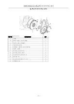
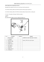
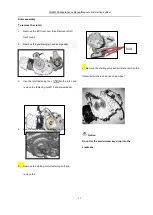
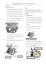
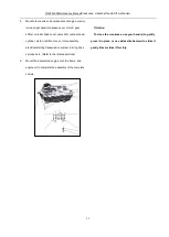
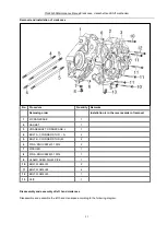
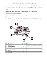
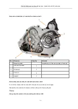
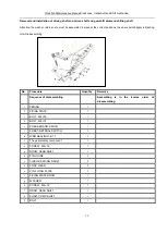
Removal and installation of crankcase
No.
Procedure
Quantity
Remarks
Removing order
Installation is in the reverse order of removal
1
R.CRANKCASE
1
2
GASKET
1
3
CRANKSHAFT, CRANKCASE, L
1
4
BOLT A, CYLINDER STUD
(
A
)
2
5
BOLT B, CYLINDER STUD (B)
2
6
PIN A, KNOCK92401-10014
2
7
WASHER
1
8
PIN A, KNOCK92401-10014
1
9
CLAMP, OVER FLOW PIPE
1
10
BOLT,FLGM6×50
2
11
BOLT,FLGM6×65
4
12
BOLT,FLGM6×60
1
13
CLIP
1
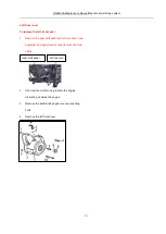
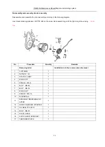
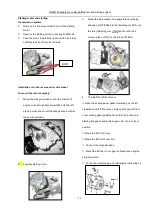
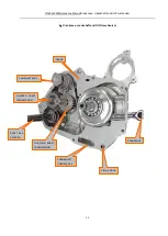
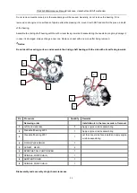
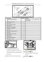
Disassembly and assembly of left hand crankcase
Disassemble and assemble the left hand crankcase according to the following diagram.
Summary of Contents for YG48Q-5A
Page 38: ...YG48Q 5AMaintenance ManualFuel system 41 4 Fuel system...
Page 92: ...YG48Q 5AMaintenance ManualFrame and exhaust system 105 10 Frame and exhaust system...
Page 123: ...YG48Q 5A Maintenance ManualIllumination signal system 136 Circuit schematic drawing...
Page 126: ...YG48Q 5A Maintenance ManualIllumination signal system 139...
Page 133: ...YG48Q 5A Maintenance ManualEngine management system 146 Major parts and components...
Page 134: ...YG48Q 5A Maintenance ManualEngine management system 147...
Page 144: ...YG48Q 5A Maintenance ManualElectrical System Diagram 157 19 Electrical System Diagram...

