YG48Q-5A Maintenance ManualCylinder Head, Cylinder and Piston
63
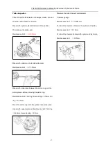
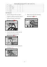
Cylinder head inspection
Check whether the cylinder head is unobstructed, clean
and free of leaks; check the cylinder head’s spark plug
hole and valve seat for cracks; insert the valve into the
valve guide bore and move it up and down to check its
movement; sway it back and forth and left and right to see
whether there is significant sloshing.
Check the cylinder head for deformation, and use the
edge ruler and clearance gauge to inspect the planeness
of the cylinder’s joining surface.
Maintenance limit:
≤
0.05mm.
Measure the valve guide aperture.
Maintenance limit:
≤φ
5.012mm
Measure the valve stem diameter.
Maintenance limit: IN
≥φ
4.970mm,
EX
≥φ
4.955mm
Measure the width of the valve contacting surface.
Maintenance limit:
≤
1.7mm
Measure the free length of the valve spring
Maintenance limit: Internal spring
≥
32.78mm
External spring
≥
35.00mm.
Calculate the clearance between the valve stem and valve
guide
Maintenance limit:IN
≥
0.09mm,
EX
≥
0.10mm.
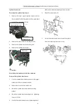
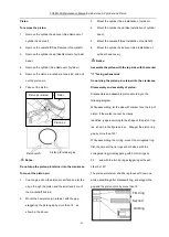
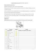
Cylinder
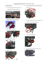
To remove the cylinder:
1.
Remove the cylinder head cover (See Removal of
cylinder head cover)
2.
Remove the camshaft (See Removal of camshaft);
3.
Remove the cylinder head (See Removal of cylinder
head)
4.
Remove the chain slide;
5.
Remove cylinder connecting bolt
6.
Remove the tensioner
7.
Remove the cylinder; remove the cylinder gasket.
Clearance gauge
Air gage
Outside micrometer
Vernier calipers
Vernier calipers
Chain slide
Summary of Contents for YG48Q-5A
Page 38: ...YG48Q 5AMaintenance ManualFuel system 41 4 Fuel system...
Page 92: ...YG48Q 5AMaintenance ManualFrame and exhaust system 105 10 Frame and exhaust system...
Page 123: ...YG48Q 5A Maintenance ManualIllumination signal system 136 Circuit schematic drawing...
Page 126: ...YG48Q 5A Maintenance ManualIllumination signal system 139...
Page 133: ...YG48Q 5A Maintenance ManualEngine management system 146 Major parts and components...
Page 134: ...YG48Q 5A Maintenance ManualEngine management system 147...
Page 144: ...YG48Q 5A Maintenance ManualElectrical System Diagram 157 19 Electrical System Diagram...

