11
O R I G I N A L I N S T R U C T I O N S
EN
Observe local waste oil disposal regulations. Oil is not an environmentally inert substance. Used oil should be properly disposed
of or recycled. Contact your local waste authority for information on recycling. Never reuse the used engine oil.
During the oil extraction, do not approach the machine with
fi
re; also avoid strong sources of heat such as radiators or heaters.
Do not smoke while operating the machine.
PRODUCT OPERATION
Caution! Make sure that the product has been disconnected from the compressed air supply before starting any as-
sembly, disassembly operations or works related to
fi
lling the tank. Also, make sure that the pressure accumulated in
the product tanks has been released. To do so, open all valves. The valve is open if its lever is parallel to the valve line.
Moving the lever to the position perpendicular to the valve line closes the valve.
Threaded connections must be tightened with force not greater than is required to achieve tightness. Tightening the
threaded connections with too great a force can damage the seals. PTFE tape can be used to improve the tightness of
threaded connections.
Product assembly
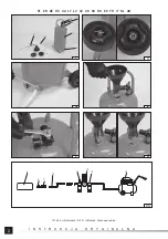
First of all, attach the wheels to the tank. Attach each wheel individually to the axle and then secure with a locking pin. The locking
pin’s arms should be parted so that the pin cannot slip out of the axis by itself (II).
Screw the free end of the hose (III) to the opening near the tank bottom.
Attach the funnel inserting its narrower end to the inlet opening (IV).
Screw the connector (V) to the air inlet; the connector enables quick disconnection of the equipment from the compressed air
source.
Filling the tank with oil (VI)
Open the oil
fi
ller valve; its lever should be directed along the valve axis. Pour oil into the tank without exceeding the rated capacity.
The oil must be entirely in the tank and must not remain in the funnel. Once the
fi
lling is complete, wait until the oil from the funnel
walls drips into the tank and close the
fi
ller valve. The valve lever should be directed perpendicular to the valve axis.
Connecting to the pneumatic system
The equipment must be connected to a compressed air source, as shown in Figure (VII). The
fi
gure shows the recommended
manner of connecting the tool to the pneumatic system. The method shown will ensure the most e
ffi
cient use of the equipment
and also prolong the tool’s service life.
Make sure the air intake valve is closed - the lever should be perpendicular to the valve axis (VIII). Set the air pressure on the
external regulator not to exceed the maximum value speci
fi
ed in the technical data table. Connect the hose to the air inlet con-
nector. Make sure that the lance trigger is not pressed. Open the air inlet valve by turning the lever so that it is parallel to the
valve axis (VIII).
Equipment operation
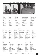
The operating pressure can be adjusted by means of a built-in regulator. The regulator knob is marked with an arrow and the
“+” and “-” symbols. Rotating the regulator knob in the direction marked “+” increases the operating pressure and rotating in the
direction marked “-” decreases the pressure. Observe the pressure value using the pressure gauge installed near the regulator.
Fill the equipment with oil, connect to the air inlet, and open the air inlet valve. Direct the end of the lance in the place for
fi
lling the
oil, then press and hold the lance trigger. The oil will start to escape from the lance outlet. Releasing the pressure on the trigger
will stop the oil
fl
ow. A small amount of oil may still come out of the lance outlet.
When the work is
fi
nished, close the air inlet valve and disconnect the equipment from the compressed air supply. Release the air
accumulated under pressure in the tank. Pull and hold the release valve (IX) until you can no longer hear the sound of escaping air.
MAINTENANCE, TRANSPORT AND STORAGE
Clean the external surfaces of the product with a diluted water-based cleaning agent designed to remove engine oil residues. Do
not use
fl
ammable cleaning agents, solvents, petrol, or alcohol. Do not use corrosive or abrasive agents.
The interior of the product should be rinsed at least once every six months with a water-based cleaning agent. This will allow the
removal of contaminants that have entered the tanks together with the used oil.
Transport the product over short distances, e.g., within the workshop, when using the product wheels. In the case of transport
over longer distances, the product should be cleaned, disassembled, and transported in the factory packaging. Regardless of
the distance, the product should always be transported disconnected from the compressed air source and with equal pressure
in the tank.
The product should be stored disconnected from the compressed air source and with equal pressure in the tank. The tank and the
other elements should be emptied and cleaned for storage. The product can be stored assembled or disassembled. Keep out of
reach of unauthorised persons, especially children. The place of storage should protect against high temperatures, direct sunlight,
and provide good ventilation so that no condensation of water vapour can form on the product.
Summary of Contents for YT-07195
Page 16: ...16 RU YT 07195 0 5 0 1 0 5 150 20 O C 35 101 2 3 119 8 3 7...
Page 17: ...17 RU GEKA...
Page 18: ...18 RU OFF PTFE II III IV V VI VII VIII...
Page 19: ...19 RU VIII IX...
Page 20: ...20 UA YT 07195 M a 0 5 M a 0 1 0 5 150 20 O C 35 dB A 101 2 3 dB A 119 8 3 7...
Page 21: ...21 UA...
Page 22: ...22 UA OFF PTFE II III IV V VI VII VIII VIII...
Page 23: ...23 UA IX...
Page 61: ...61 GR YT 07195 MPa 0 5 MPa 0 1 0 5 l min 150 l 20 O C 35 dB A 101 2 3 dB A 119 8 3 kg 7...
Page 62: ...62 GR...
Page 63: ...63 GR OFF PTFE II III IV V VI VII VIII VIII...
Page 64: ...64 GR IX...


