


ENGINE
3-5
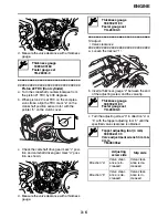
8. Remove:
• Fuel tank damper “1”
• Cylinder head breather hose “2”
9. Disconnect:
• Oil tank breather hose “3”
• Fuel outlet hose “4”
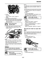
10.Remove:
• Front cylinder head cover “1”
• Rear cylinder head cover “2”
NOTE:
Due to the small clearance between the frame
and the rear cylinder head cover, the three bolts
“3” cannot be removed when the cover is in
place. Loosen the bolts, and then remove the
cylinder head cover from the right side of the ve-
hicle, making sure that the bolts do not scratch
the rocker arms or other engine parts.
11.Measure:
• Valve clearance
Out of specification
→
Adjust.
▼▼▼
▼
▼
▼▼▼
▼
▼
▼▼▼
▼
▼
▼▼▼
▼
▼
▼▼▼
▼
▼
▼▼▼
▼
▼▼▼
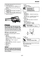
Piston #1 TDC (rear cylinder)
a. Turn the crankshaft counterclockwise.
b. When piston #1 is at TDC on the compres-
sion stroke, align the TDC mark “a” on the
crankshaft position sensor rotor with the
pointer “b” on the clutch cover.
c. Check the camshaft drive gear mark “c” posi-
tion and camshaft driven gear mark “d” posi-
tion as shown.
If the marks are not aligned, turn the crank-
shaft counterclockwise 360 degrees and re-
check step (b).
1
1
2
3
4
2
1
Valve clearance (cold)
Intake
0.00–0.04 mm (0.0000–0.0016 in)
Exhaust
0.00–0.04 mm (0.0000–0.0016 in)
2
3
3
b
a
Summary of Contents for XV19SW 2006
Page 6: ......
Page 8: ......
Page 24: ...SPECIAL TOOLS 1 15...
Page 55: ...LUBRICATION POINTS AND LUBRICANT TYPES 2 30...
Page 60: ...LUBRICATION SYSTEM CHART AND DIAGRAMS 2 35 D D B B D D C C A A B C C B 3 2 1 3 4 6 7 6 7 5...
Page 62: ...LUBRICATION SYSTEM CHART AND DIAGRAMS 2 37 A A A A 1 3 2 4...
Page 64: ...LUBRICATION SYSTEM CHART AND DIAGRAMS 2 39 A 1 2 3 4...
Page 66: ...LUBRICATION SYSTEM CHART AND DIAGRAMS 2 41 A A A 1 5 5 1 3 2 4 B B B B...
Page 68: ...LUBRICATION SYSTEM CHART AND DIAGRAMS 2 43 1 2...
Page 69: ...LUBRICATION SYSTEM CHART AND DIAGRAMS 2 44 1 Transfer gear oil pump 2 Middle driven shaft...
Page 78: ...CABLE ROUTING 2 53...
Page 86: ...CABLE ROUTING 2 61...
Page 89: ......
Page 122: ...ELECTRICAL SYSTEM 3 33 a b 1...
Page 125: ......